 ChipApex | Global Electronic Components Supplier
SEARCH
Search Product
Search Post
— IC芯片 | 连接器 | 传感器 | 被动器件 —
Search productSearch post
— IC芯片 | 连接器 | 传感器 | 被动器件 —
Consult the customer manager about the wholesale price.
consultation hotline:86-132-6715-2157
email:[email protected]
Contact the product manager for consultation. One-stop consultation is available.
Do you want a lower wholesale price? Please send us your inquiry and we will reply immediately.
The DMHC3025LSD-13 is a complementary enhancement mode MOSFET H-Bridge featuring two N-channel and two P-channel devices within an SO-8 package. The N-channel section provides a drain-source breakdown voltage of 30V, with a maximum on-resistance of 25mΩ at VGS=10V and 40mΩ at VGS=4.5V. Continuous drain current reaches 6.0A at VGS=10V and 4.6A at VGS=4.5V. The P-channel section offers a -30V breakdown voltage, with on-resistance values of 50mΩ at VGS=-10V and 80mΩ at VGS=-4.5V. Maximum continuous drain currents are -4.2A and -3.2A respectively. Total power dissipation is rated at 1.5W.
Verify the specific ordering suffix '-13' corresponds to the tape and reel packaging configuration containing 2500 units per reel. Confirm that the component meets RoHS directives and is halogen-free if environmental compliance is required for the assembly process. Ensure the manufacturing source matches Diodes Incorporated specifications.
Select this component when a matched complementary pair is needed for H-bridge topologies requiring low gate drive voltages. Verify that the 30V breakdown voltage aligns with the system supply rails. Consider the thermal resistance of 83°C/W for ambient cooling requirements and ensure the SO-8 footprint fits the PCB layout constraints.
This part belongs to the DMHC series of complementary MOSFETs manufactured by Diodes Incorporated. It serves as a specialized solution for driving loads in bridge configurations without requiring separate discrete N-channel and P-channel components. The device is designed to simplify circuit design while maintaining efficient power handling capabilities.
The datasheet notes that an automotive-compliant version is available under the separate part number DMHC3025LSDQ. Verify pinout compatibility and electrical parameter tolerances before substituting with other complementary MOSFET pairs from different manufacturers.
The maximum pulsed drain current (IDM) for the N-channel section is 60A, based on a 10μs pulse duration with a 1% duty cycle.
Yes, the device includes internal body diodes. The maximum continuous body diode forward current (IS) is specified as 2.5A for both N-channel and P-channel sections.
The typical total gate charge (Qg) for the N-channel section at VGS=10V is 11.7nC, measured at VDS=15V and ID=7.8A.
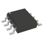 DMHC3025LSD-13
The activity of extra discounts on wholesale prices is in full swing…
Please fill in your contact information and we will send you the latest wholesale price list.





