ChipApex | Global Electronic Components Supplier

SEARCH
Search Product
Search Post
— IC芯片 | 连接器 | 传感器 | 被动器件 —
Search productSearch post
— IC芯片 | 连接器 | 传感器 | 被动器件 —
Consult the customer manager about the wholesale price.
consultation hotline:86-132-6715-2157
email:[email protected]
Contact the product manager for consultation. One-stop consultation is available.
Do you want a lower wholesale price? Please send us your inquiry and we will reply immediately.
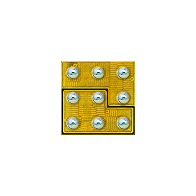
EPC2106 is listed in the FET, MOSFET Arrays range at ChipApex. The manufacturer field lists EPC. Its product description is MOSFET 2N-CH 100V 1.7A DIE. Review the specifications below when checking this part for your BOM.
The EPC2106 is an enhancement-mode Gallium Nitride (GaN) power transistor configured as a half-bridge. It features a 100 V drain-to-source voltage rating and a maximum on-resistance of 70 mΩ at VGS = 5 V and ID = 2 A. The device supports a continuous drain current of 1.7 A at 25°C and operates within a junction temperature range of -40°C to 150°C. Key dynamic characteristics include a total gate charge of 900 pC maximum and zero reverse recovery charge. The component is supplied in passivated die form with solder bumps, measuring 1.35 x 1.35 mm.
Verify the specific ordering suffix against the manufacturer's official documentation to confirm packaging format and reel specifications. Confirm that the received components match the laser markings and die orientation dot described in the datasheet. Ensure assembly processes utilize SAC305 Type 4 solder and appropriate stencil thicknesses as recommended by the manufacturer.
Select this component for designs requiring a compact half-bridge solution with minimal footprint. Consider the 1.7 A continuous current limit and 70 mΩ on-resistance when calculating conduction losses. Evaluate the thermal resistance parameters relative to the intended PCB copper pad area to ensure adequate heat dissipation for the target operating conditions.
The EPC2106 belongs to the eGaN® FET family from Efficient Power Conversion Corporation. It utilizes lateral GaN technology to achieve low on-resistance and fast switching speeds. The device is designed to replace traditional silicon MOSFET pairs in half-bridge topologies, offering reduced component count and improved efficiency due to the absence of reverse recovery charge.
No official substitute part numbers are documented in the provided datasheet. When evaluating alternatives, verify compatibility with the 1.35 x 1.35 mm die size and the specific land pattern requirements. Ensure any replacement maintains the half-bridge configuration and meets the 100 V breakdown voltage requirement.
The EPC2106 is typically used in a half-bridge configuration, consisting of a high-side switch (Q1) and a low-side switch (Q2), driven by a level-shifted gate driver.
The EPC2106 does not have a parasitic body diode like silicon MOSFETs. However, it exhibits reverse conduction capability through its channel, resulting in zero reverse recovery charge (QRR).
The datasheet specifies a maximum gate-to-source voltage of +6 V and a minimum of -4 V. For optimal performance, a 5 V drive is typically used for the ON state, while 0 V is sufficient for the OFF state.
Explore related parts through FETs, MOSFETs, Transistors, Discrete Semiconductor Products, all product categories.
 EPC2106

The activity of extra discounts on wholesale prices is in full swing…
Please fill in your contact information and we will send you the latest wholesale price list.