ChipApex | Global Electronic Components Supplier
SEARCH
Search Product
Search Post
— IC芯片 | 连接器 | 传感器 | 被动器件 —
Search productSearch post
— IC芯片 | 连接器 | 传感器 | 被动器件 —
Consult the customer manager about the wholesale price.
consultation hotline:86-132-6715-2157
email:[email protected]
Contact the product manager for consultation. One-stop consultation is available.
Do you want a lower wholesale price? Please send us your inquiry and we will reply immediately.
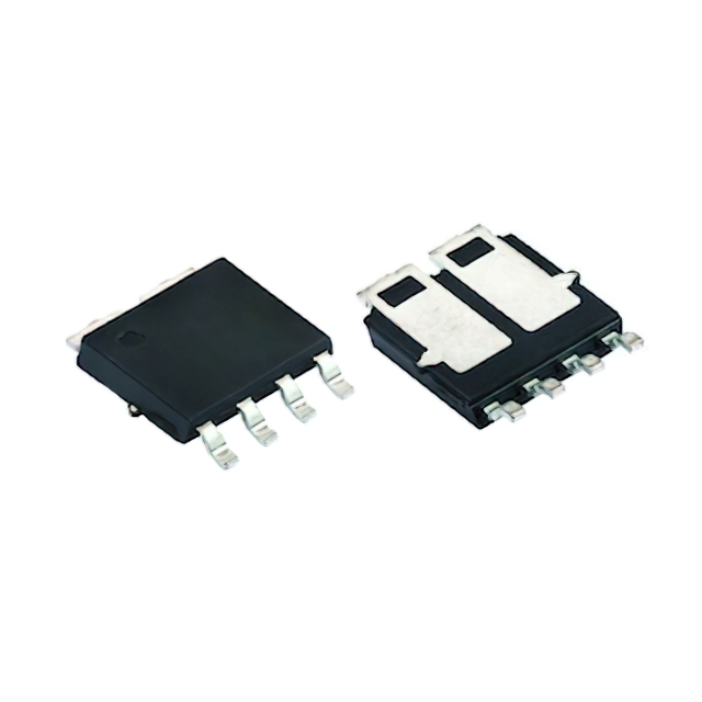
The SQJ748EP is an automotive-grade dual N-channel MOSFET from Vishay Siliconix, utilizing TrenchFET technology and qualified to AEC-Q101 standards. It features a 40 V drain-source voltage rating and operates within a junction temperature range of -55 °C to +175 °C. The device provides a continuous drain current of 72 A per leg at 25 °C case temperature, with a maximum on-state resistance (RDS(on)) of 6.88 mΩ at VGS = 10 V. Packaged in a PowerPAK SO-8L Dual BWL footprint, it offers a thermal resistance (junction-to-case) of 2.3 °C/W and supports single-pulse avalanche energy up to 15 mJ.
Verify the complete ordering suffix via the official Vishay document 79771 to ensure correct packaging configuration. Confirm that the exposed copper tip solder fillet requirement aligns with your assembly process specifications. Validate component authenticity through authorized distributors to maintain AEC-Q101 compliance.
Select this component when a dual N-channel configuration with high current capability is required in a compact surface-mount package. Ensure the PCB layout accommodates the specific thermal characteristics of the PowerPAK SO-8L Dual BWL package. Verify that the gate drive voltage meets the 10 V threshold for optimal RDS(on) performance.
This part belongs to the SQJ series of automotive MOSFETs designed by Vishay Siliconix. It shares the TrenchFET technology platform with other devices in the lineup but is distinguished by its specific 40 V rating and dual-channel topology within the PowerPAK SO-8L Dual BWL package.
Direct substitutes must match the 40 V rating, dual N-channel configuration, and PowerPAK SO-8L Dual BWL package. Verify equivalent RDS(on), thermal resistance, and AEC-Q101 qualification status before implementation.
The device supports a single-pulse avalanche energy (EAS) of 15 mJ when tested with an inductance of 0.1 mH.
The RDS(on) increases with temperature; it reaches a maximum of 10.5 mΩ at 125 °C and 12.6 mΩ at 175 °C under standard test conditions.
Yes, the typical reverse recovery time (trr) is 204 ns when conducting 10 A with a di/dt of 100 A/μs.
 SQJ748EP-T1_GE3
The activity of extra discounts on wholesale prices is in full swing…
Please fill in your contact information and we will send you the latest wholesale price list.