 ChipApex | Global Electronic Components Supplier
SEARCH
Search Product
Search Post
— IC芯片 | 连接器 | 传感器 | 被动器件 —
Search productSearch post
— IC芯片 | 连接器 | 传感器 | 被动器件 —
Consult the customer manager about the wholesale price.
consultation hotline:86-132-6715-2157
email:[email protected]
Contact the product manager for consultation. One-stop consultation is available.
Do you want a lower wholesale price? Please send us your inquiry and we will reply immediately.
The STGF15M65DF2 is a trench gate field-stop IGBT from the M series, rated at 650 V collector-emitter voltage and 15 A continuous collector current. It features a typical saturation voltage of 1.55 V at 15 A and supports a pulsed collector current of 30 A. The device operates within a junction temperature range of -55°C to 175°C and dissipates up to 31 W. Key electrical parameters include a gate charge of 45 nC, turn-on time of 24 ns, turn-off time of 93 ns, and reverse recovery time of 142 ns. Packaged in TO-220FP for through-hole mounting.
Verify the specific ordering suffix against official STMicroelectronics documentation to ensure correct package variant and tape/reel specifications. Confirm that the component status remains active before finalizing procurement plans. Cross-reference the manufacturer part number with authorized distributor catalogs to validate authenticity and traceability. Ensure storage and handling procedures comply with moisture sensitivity levels defined in the datasheet.
Select this component when designing circuits requiring a 650 V rating with 15 A continuous current capacity. The positive temperature coefficient facilitates parallel operation for higher current demands. Consider the 6 µs short-circuit withstand time for robust fault protection. Evaluate the thermal resistance characteristics to determine appropriate heatsinking solutions for the intended operating environment.
This device belongs to the STMicroelectronics M series of IGBTs, which are engineered to balance performance and efficiency. The series utilizes trench gate field-stop technology to minimize switching losses while maintaining high short-circuit ruggedness. This specific model targets applications where system efficiency and reliability under fault conditions are critical design constraints.
Direct replacements within the same series include STGWA50M65DF2 (50 A, TO-247) and STGYA120M65DF2 (120 A, Max247). Verify pin compatibility and thermal interface requirements when substituting with higher current variants. Ensure the replacement device meets the original circuit's voltage and switching speed specifications.
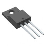 STGF15M65DF2
The activity of extra discounts on wholesale prices is in full swing…
Please fill in your contact information and we will send you the latest wholesale price list.





