 ChipApex | Global Electronic Components Supplier
SEARCH
Search Product
Search Post
— IC芯片 | 连接器 | 传感器 | 被动器件 —
Search productSearch post
— IC芯片 | 连接器 | 传感器 | 被动器件 —
Consult the customer manager about the wholesale price.
consultation hotline:86-132-6715-2157
email:[email protected]
Contact the product manager for consultation. One-stop consultation is available.
Do you want a lower wholesale price? Please send us your inquiry and we will reply immediately.
The STGW19NC60W is a single N-channel ultra-fast IGBT manufactured by STMicroelectronics, utilizing the PowerMESH™ process. It features a collector-emitter voltage (VCEO) of 600 V and a continuous collector current (IC) of 42 A at TC = 25°C in a TO-247 package. The device operates within a junction temperature range of -65 °C to 150 °C. Key electrical parameters include a maximum gate-emitter voltage of ±20 V, a typical saturation voltage (VCE(sat)) of 2.1 V at IC = 12 A, and a total switching energy (Ets) of 206 μJ under standard test conditions.
Verify component authenticity through authorized channels as counterfeit risks exist. Confirm datasheet revision status, specifically Rev 3, which includes TO-247 packaging details. Ensure thermal management aligns with specified Rthj-case limits. Check RoHS compliance markings on ECOPACK® packages. Validate ordering codes against official ST documentation before procurement.
Select this component for designs requiring 600 V blocking capability with moderate current handling up to 42 A. Consider the TO-247 package for through-hole mounting and superior thermal dissipation compared to smaller form factors. Evaluate gate resistance requirements to manage switching losses and dv/dt rates effectively within the specified operating temperature range.
This part belongs to the STGx19NC60W family, which includes variants like STGB19NC60W and STGP19NC60W. These devices share identical electrical characteristics but differ in physical packaging configurations such as D2PAK, TO-220, and TO-247. The series is designed for general-purpose high-frequency power switching applications.
Direct functional substitutes within the same family include STGB19NC60W and STGP19NC60W, differing only in package type. Verify pinout compatibility and thermal resistance specifications when substituting across different package styles to ensure adequate heat dissipation.
The absolute maximum collector-emitter voltage (VCES) is rated at 600 V with the gate-emitter voltage at 0 V.
The low CRES/CIES ratio minimizes capacitive coupling effects, thereby preventing unwanted cross-conduction in half-bridge or full-bridge configurations without requiring additional snubber circuits.
Under standard test conditions (VCC = 390 V, IC = 12 A, RG = 10 Ω), the typical turn-off switching energy (Eoff) is 125 μJ.
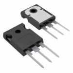 STGW19NC60W
The activity of extra discounts on wholesale prices is in full swing…
Please fill in your contact information and we will send you the latest wholesale price list.





