 ChipApex | Global Electronic Components Supplier

SEARCH
Search Product
Search Post
— IC芯片 | 连接器 | 传感器 | 被动器件 —
Search productSearch post
— IC芯片 | 连接器 | 传感器 | 被动器件 —
The trend of science and technology is changing rapidly.
A seven-segment display forms digits by lighting combinations of seven LED bars, usually labeled a through g. Many packages add a decimal point. The common-anode or common-cathode connection determines the drive polarity, while the exact part number determines the physical pinout. Segment current, driver capability and multiplex duty determine how the circuit should be built.
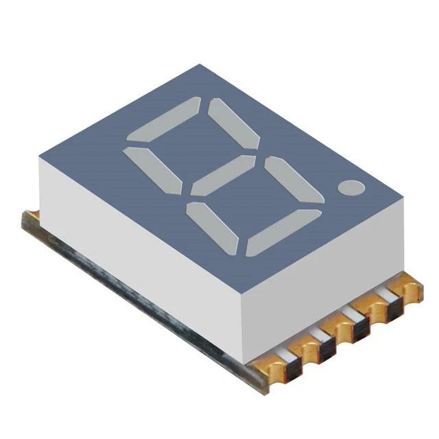
In a common-cathode display, the segment cathodes share a connection. The circuit supplies current to the selected segment anodes. In a common-anode display, the anodes share a connection and the circuit sinks current from the selected cathodes. The common connection can appear on multiple pins or through a multi-digit arrangement, so use the actual internal circuit drawing.
The standard segment labels describe positions on the digit. Segment a is the top bar, d is the bottom, and g is the center. Lighting b and c forms 1. Lighting a, b, g, e and d forms 2. The decimal point is separate.
A package that has ten leads does not have a universal pin assignment. Confirm the drawing’s viewing direction and part suffix. The Kingbright SC56-11EWA data sheet provides a concrete example with a connection diagram, ratings and mechanical dimensions.
ChipApex groups related display devices under LED character and numeric displays. Match the character height, color, common connection and pin pattern before treating two displays as replacements.
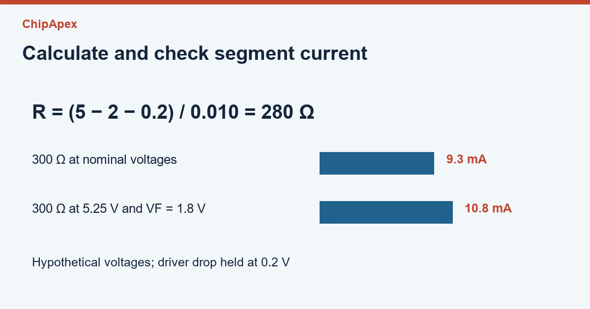
For a simple resistor-driven segment, estimate R = (VSUPPLY − VF − VDRIVER) ÷ ISEGMENT. Use the voltage remaining across the resistor after accounting for the LED and the output stage. Each independently controlled segment normally needs its own current-setting path. One shared resistor in a common lead can make current depend on how many segments are lit.
Take a hypothetical 5 V supply, a 2 V LED drop, a 0.2 V driver drop and a 10 mA target. The resistor estimate is (5 − 2 − 0.2) ÷ 0.01 = 280 Ω. Choosing 300 Ω would give about 9.3 mA under those same assumptions. Resistor power is approximately 0.0093² × 300 = 0.026 W.
Now check variation. If the supply rises to 5.25 V and the LED drop falls to 1.8 V while the assumed driver drop remains 0.2 V, current through 300 Ω becomes approximately 10.8 mA. Actual driver drop, LED tolerance and temperature can also change it. Select the resistor and output stage against the relevant limits.
| Design field | What to verify |
|---|---|
| LED current | Continuous or pulse limit under its stated conditions |
| Supply and LED drop | Worst-case current through the resistor |
| Output stage | Source or sink ability and voltage drop |
| Common terminal | Total current for simultaneously lit segments |
| Resistor | Power, tolerance and installation temperature |
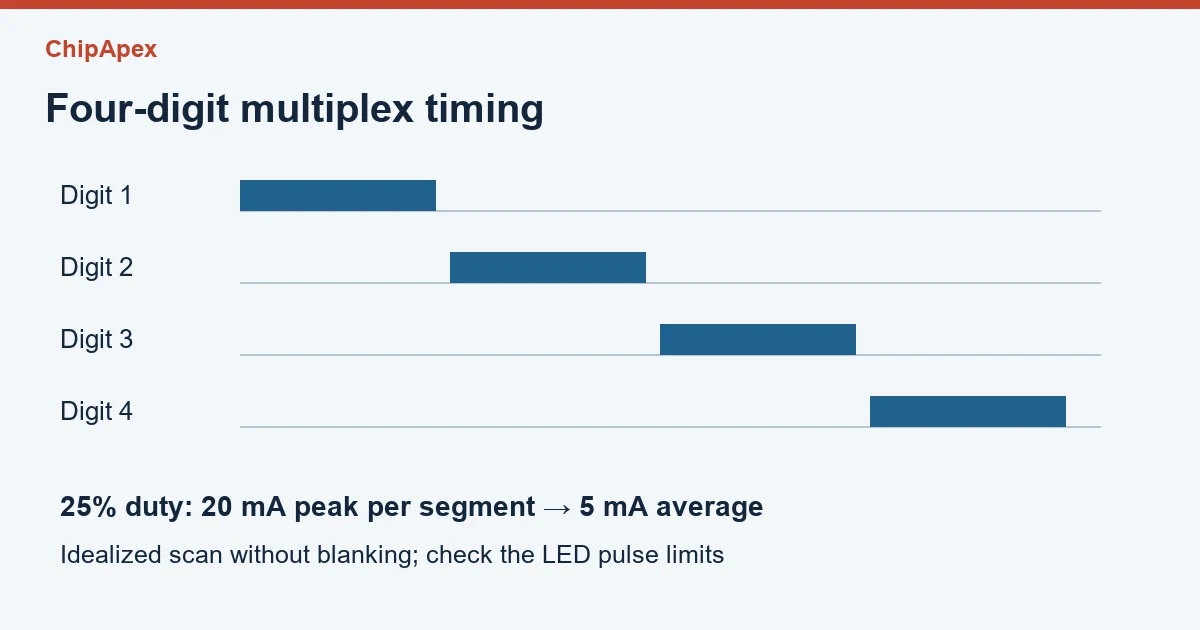
A multiplexed display activates one digit at a time while presenting its segment pattern. With four equally timed digits, each digit has a duty of roughly one quarter, reduced further by any blanking intervals. An on-state segment current of 20 mA would therefore average approximately 5 mA over the scan cycle at a 25% duty.
That calculation does not authorize multiplying a continuous current rating by four. The LED’s pulse specification has its own maximum current, pulse width and duty conditions. The common pin or digit switch also carries the sum of the active segment currents. With seven lit segments at 20 mA each, that is 140 mA during that digit’s on interval, before the decimal point.
A dedicated driver can manage scanning and current control, but it must match the common connection and electrical requirements. The MAX7219/MAX7221 data sheet documents one common-cathode driver architecture. Other devices may use a different arrangement. Use the output topology and operating range to choose a part.
Read the exact part number and obtain its connection drawing. Check whether the drawing is a front, bottom or other view. Segment labels a–g tell you where bars appear, while the physical lead numbers tell you how to wire that package. The two are not interchangeable.
The circuit generally needs different current-flow polarity and suitable source or sink stages. A similar package does not make the swap electrically compatible. Confirm both the display’s common arrangement and the driver’s output architecture before choosing a replacement.
Compare active time, peak segment current and the number of lit segments. Shared current-limiting paths, scan timing or a weak digit switch can change brightness. Inspect the actual current and waveforms rather than comparing only the display’s supply voltage.
Seven bars can form a limited set of recognizable characters. Several letters are ambiguous or resemble digits. If the interface needs clear mixed text, consider a display with more segments or another character technology and check the resulting driver requirements.
Segment data can briefly overlap with the wrong digit-enable interval. Driver timing, transistor turn-off and firmware sequencing can contribute. Review the timing and any recommended blanking period for the actual hardware before increasing scan speed.
For a ChipApex quote, share the display part number or drawing, character height, color, common connection, digit count, driver interface and quantity.
Discover why SRAM remains essential in industrial, medical & aerospace systems—thanks to its deterministic performance and long-term reliability. Trusted by engineers worldwide.
View details
Choose an AC to DC converter by input range, output demand, isolation, efficiency and thermal derating. Compare architectures and check installation needs.
View details
Practical MCU selection guide for engineers: compare STM32, ESP32 & NXP, avoid counterfeits, and ensure supply chain reliability. Authored by ChipApex FAE.
View details
Identify fork terminals and flat-blade spade connectors. Match wire size, tab thickness, insulation and crimp tooling before selecting a replacement.
View details
The activity of extra discounts on wholesale prices is in full swing…
Please fill in your contact information and we will send you the latest wholesale price list.