 ChipApex | Global Electronic Components Supplier

SEARCH
Search Product
Search Post
— IC芯片 | 连接器 | 传感器 | 被动器件 —
Search productSearch post
— IC芯片 | 连接器 | 传感器 | 被动器件 —
The trend of science and technology is changing rapidly.
A terminal block secures conductors and provides a defined electrical connection between them. Its housing, contact system and mounting arrangement determine how it fits a PCB, panel or DIN rail. Choose the connection technology and conductor range first, then check ratings, installation details and accessories for the complete assembly.
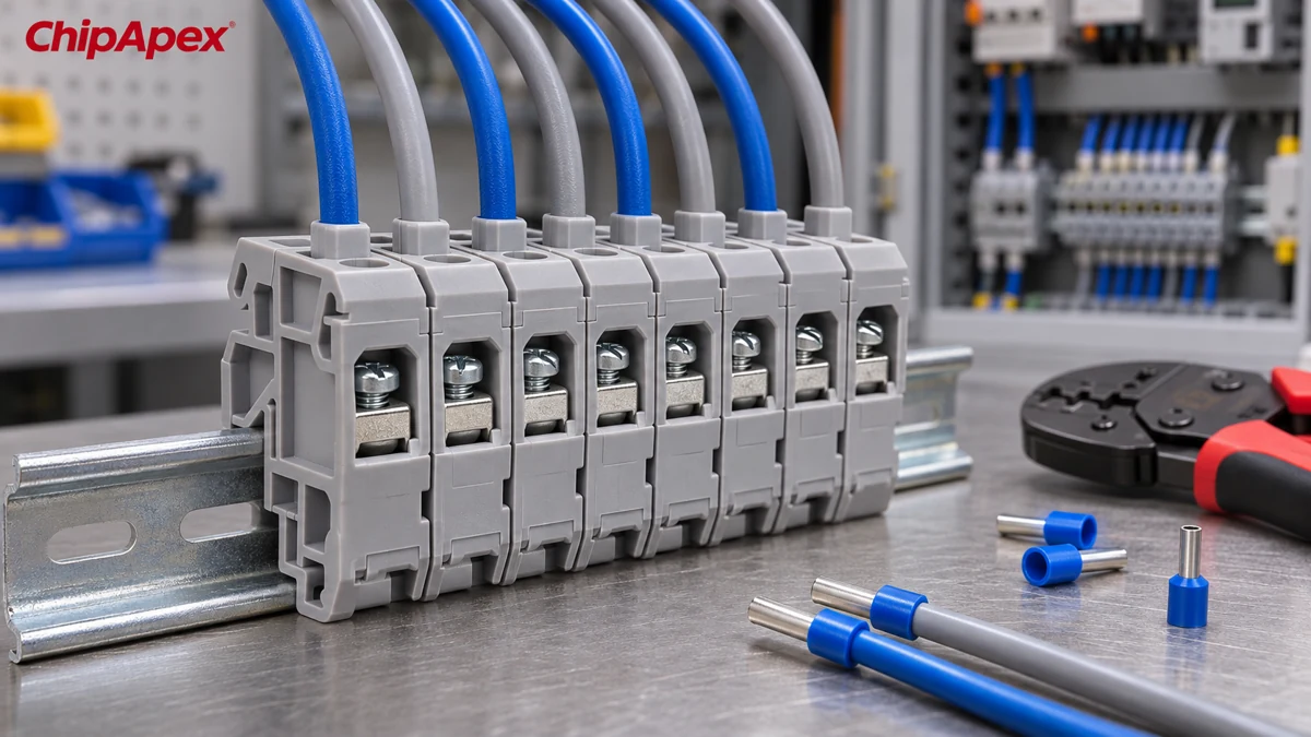
A screw connection uses a specified screw or clamp to hold the conductor. Some designs include spring support within a screw-operated system. Spring-cage and push-in terminals use a spring contact system, with insertion and release methods that depend on the conductor and design. Read the product’s connection instructions before assuming a flexible wire can be pushed in directly.
PCB terminal blocks solder to a board or mate with a board-mounted header. Panel and DIN-rail blocks organize field wiring. A DIN-rail terminal block can include feed-through, protective-earth, disconnect or fused functions. Similar widths or colors do not guarantee that accessories interchange.
| Assembly | First dimensions or interfaces to check |
|---|---|
| PCB screw terminal block | Pitch, pin pattern, wire-entry direction and board clearance |
| Pluggable terminal block | Exact mating family, coding and locking arrangement |
| DIN-rail feed-through block | Rail profile, conductor range and accessory system |
| Barrier strip | Pole spacing, fasteners, tongue clearance and insulating barriers |
A product drawing and rated conductor range are more useful than a general description such as “two-way green terminal.” ChipApex’s connectors and interconnects catalog can support a search for related connection hardware. Include the mating half if the part is pluggable.
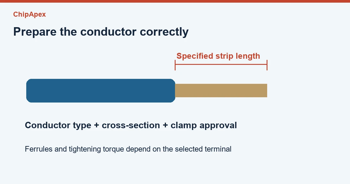
Check the conductor type as well as its cross-section. A data sheet may list different ranges for solid wire, flexible wire and flexible wire with ferrules. Ferrule length and collar size can affect insertion. If two conductors are required in one clamping point, use a terminal explicitly covering that arrangement.
Strip to the specified length. Too little bare conductor can leave insulation under the clamp, while too much can expose copper outside the housing. A screw connection needs its specified tightening torque. Excess torque can damage the mechanism, and insufficient torque can leave a poor connection. Spring-operated terminals still require the correct insertion and release process.
Electrical ratings also depend on the applicable approval and conditions. Check the voltage, current, temperature and conductor assumptions for the intended market. For example, a manufacturer may present IEC and UL data in separate tables. Retain the selected approval context when copying a value into the BOM. The Phoenix Contact USSTD 6/SP product data illustrates the separate conductor, mechanical and electrical fields.
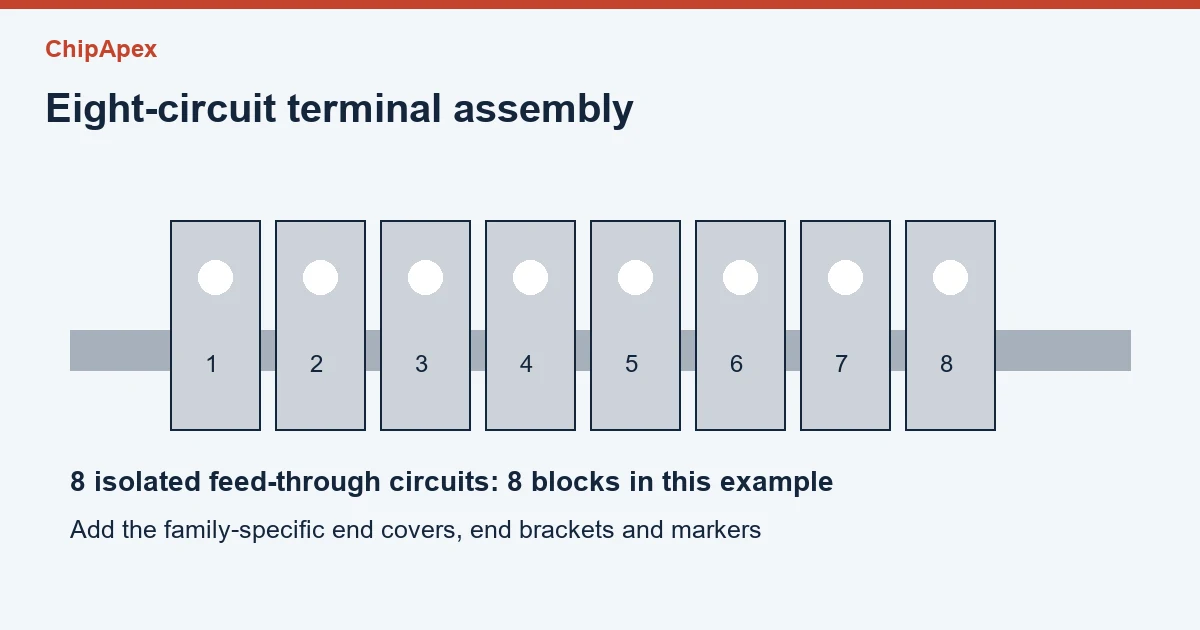
Suppose a cabinet needs eight independent feed-through circuits on a DIN rail. The drawing calls for eight terminal blocks. The physical assembly may also need an end cover where a conductive side would otherwise remain exposed, end brackets to retain the row, markers and specified rail hardware. Quantity and placement depend on the selected family and the installation.
A jumper is a deliberate electrical connection between positions. Match its pitch, insertion method and current rating to the terminal system. A ten-position jumper is not automatically suitable for ten arbitrary blocks that happen to be the same width. Identify which positions share a potential and verify the jumper’s permitted loading.
| BOM line | Verification before release |
|---|---|
| Terminal blocks | Function, conductor range and required approval |
| End covers or partitions | Correct family and locations in the assembly |
| End brackets | Rail compatibility and row retention |
| Jumpers | Positions connected and compatible current rating |
| Markers | Identification scheme and fit |
| Rail and mounting hardware | Drawing, spacing and equipment requirements |
For a PCB assembly, add the header and mating plug as separate items when necessary. Check orientation with a drawing or a mechanical mock-up. A wire exit that faces a wall can make an otherwise correct connector difficult to service. The manufacturer’s terminal-block catalog provides examples of connection technologies and accessory systems.
They can serve a similar electrical function but differ in dimensions, conductor preparation and installation. Compare the drawing, rated wire range, voltage and current conditions. For a replacement in an existing row, also check jumpers, markers, end covers and rail fit.
Follow the terminal manufacturer’s requirements for that conductor type. Some spring systems accept certain flexible conductors directly using a release tool, while other arrangements specify ferrules. Ferrule geometry and length need to fit the clamping point, and its crimp should follow the chosen termination process.
Only when the terminal specification permits the conductor combination and size. A clamp designed for one wire may grip two wires unevenly. Twin ferrules or multi-conductor terminals can be options when the system documentation covers them.
Pitch usually describes the center-to-center spacing of adjacent connection positions or PCB contacts. Check the drawing to see which points the dimension references. Pitch alone does not establish mating compatibility, current capacity or the clearance available for a conductor.
Start with the approved accessory family. Verify its number of positions, any removable contacts, the current limit and which blocks it can bridge. Put the jumper on the circuit drawing because it changes which terminals share a potential.
For a ChipApex quote, provide the function, wire specification, pole count, mounting drawing, approval requirements, mating parts and quantity.
Discover how NOR flash enables fast code execution in embedded systems, its key types (Parallel/SPI), and how to source authentic, traceable ICs from trusted suppliers.
View details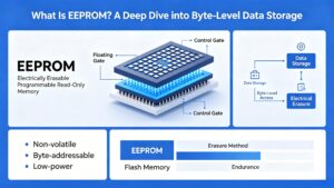
What is EEPROM? Learn byte-level storage, EEPROM vs Flash, I2C/SPI, BOM selection & sourcing risks. Authentic EEPROMs at ChipApex.
View details
Learn how a TRIAC switches AC loads. Understand triggering, latching, holding current, phase control and thermal limits before choosing a component.
View details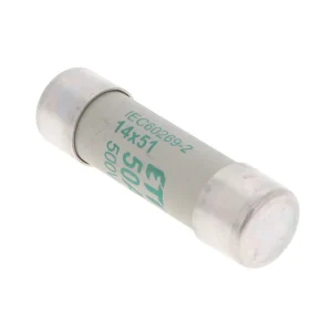
Understand HRC fuse breaking capacity, voltage and current ratings, time-current curves, and the checks needed for motor, feeder and converter protection.
View details
The activity of extra discounts on wholesale prices is in full swing…
Please fill in your contact information and we will send you the latest wholesale price list.