 ChipApex | Global Electronic Components Supplier

SEARCH
Search Product
Search Post
— IC芯片 | 连接器 | 传感器 | 被动器件 —
Search productSearch post
— IC芯片 | 连接器 | 传感器 | 被动器件 —
The trend of science and technology is changing rapidly.
A high rupturing capacity fuse, or HRC fuse, can interrupt a large prospective fault current under its stated test conditions. Start with the available fault current and circuit voltage, then check normal load, inrush and coordination. Two fuses with the same size and ampere marking can behave quite differently during a fault.
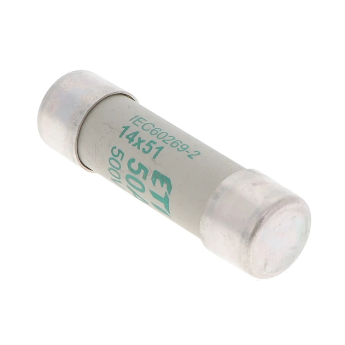
When a fault drives enough current through the element, the element melts and an arc can form across the opening. Many industrial cartridge designs use a ceramic body and a silica filler to help cool and quench that arc. The enclosure, element geometry and filler work together. Appearance alone cannot tell you the fuse’s interrupting rating or test conditions.
A current-limiting fuse can reduce the peak current and energy that pass during a sufficiently large fault. The data you need for coordination are the manufacturer’s peak let-through and total clearing I²t curves at the applicable conditions. A time-current curve answers a different question: how long the fuse takes to melt or clear at a specified current. See the fuse manufacturer’s technical FAQ for rating and curve definitions.
| Specification | What it tells you | What to check |
|---|---|---|
| Rated current (A) | Normal current duty under reference conditions | Continuous load, ambient temperature and holder derating |
| Rated voltage (V) | Maximum circuit voltage covered by the stated rating | Actual circuit voltage and separate AC or DC markings |
| Breaking capacity (kA) | Maximum prospective fault current covered by the test rating | Available fault current at the installation point |
| Time-current curve | Operating time at different overcurrents | Startup, overload and coordination requirements |
| Clearing I²t | Integral of current squared over the clearing event | Withstand limits, conditions and coordination data |
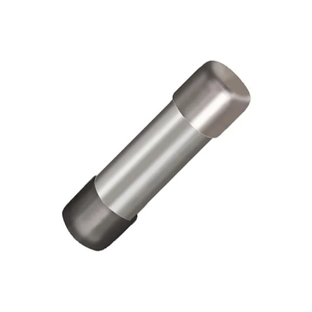
Start with a documented fault-current estimate at the fuse location. Then check which device is supposed to clear a fault first, since a fuse that meets the breaking capacity can still disrupt coordination. On a motor branch, compare the starting current and duration with the published curve. In IEC families, an aM fuse is generally intended for short-circuit protection with separate overload protection. Confirm the design and the exact product documentation.
For a power converter, the semiconductor withstand and DC fault conditions can decide the choice before nominal current does. Compare clearing I²t with the equipment limits under compatible conditions and check for any required minimum interrupting current. When sourcing a replacement, also match the physical size, mounting format and holder. ChipApex lists electrical fuses alongside general circuit protection components.
Consider a hypothetical 480 V AC cabinet with 18 kA of available fault current at the fuse location. Compare the voltage and interrupting ratings together before considering package or ampere rating.
| Candidate | Marked interrupting rating | Screening result |
|---|---|---|
| A | 50 kA at 250 V AC | Published voltage does not cover the cabinet |
| B | 10 kA at 480 V AC | Available fault current exceeds interrupting rating |
| C | 50 kA at 480 V AC | Passes the voltage and fault-current screen |
Candidate C still needs a suitable ampere rating, utilization category, holder and clearing curve. In a motor branch, compare the full startup profile with the time-current curve. Near a semiconductor, use total clearing I²t under applicable conditions and compare it with the equipment manufacturer’s withstand data. Equal ampere ratings alone cannot establish selective coordination between upstream and downstream devices.
On the replacement request, retain the exact part number and include a photo of the rating markings if the part can be safely identified. The marks help separate a dimensional match from an electrically approved replacement. Follow the published utilization category and clearing curves for the selected part.
It stands for high rupturing capacity. Breaking capacity and interrupting rating are labels you may encounter for the same general concept. Use the actual numeric rating and conditions from the datasheet.
Use the part’s explicit DC rating and conditions. A DC arc does not have the periodic current zero of AC, so an AC interrupting rating alone does not establish suitability for DC.
Use the protection scheme and approved replacement specification. A higher current rating changes when the device clears overloads and may leave wiring or equipment underprotected. Have the cause of repeated operation investigated.
No. Breaking capacity describes interruption capability. Speed is described by the part’s time-current characteristics, which may be chosen for sustained inrush or fast equipment protection.
Dimensions only establish fit. Compare voltage, current, interrupting rating, utilization category, time-current behavior, approvals and holder compatibility before replacing a part.
For a ChipApex quote, include the original part number, mounting format, circuit voltage, AC or DC rating, interrupting requirement and quantity.
Choose a pin header by pitch, mating geometry, current rating and mounting. Learn why matching pin count and spacing does not guarantee compatibility.
View details
Explore electronic component types, functions, packages and datasheets. Learn selection, replacement and BOM checks before ordering parts for your PCB.
View details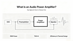
Learn what an audio power amplifier is, the differences between Class D and AB, and how to choose the right IC. Includes PCB layout tips and part recommendations. Shop at ChipApex.
View details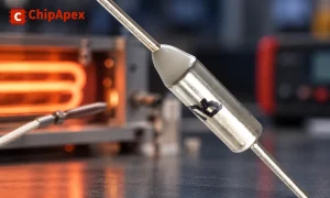
Understand thermal fuse operation, Tf, Th and Tm, electrical ratings and mounting. Check temperature limits and replacement requirements for your design.
View details
The activity of extra discounts on wholesale prices is in full swing…
Please fill in your contact information and we will send you the latest wholesale price list.