 ChipApex | Global Electronic Components Supplier
SEARCH
Search Product
Search Post
— IC芯片 | 连接器 | 传感器 | 被动器件 —
Search productSearch post
— IC芯片 | 连接器 | 传感器 | 被动器件 —
The trend of science and technology is changing rapidly.
A voltage regulator keeps an electronic power rail near its target as supply and load vary. Linear and switching regulators can produce the same output voltage while drawing very different input power. The right choice depends on the voltage drop, how long the load stays active, how much noise the load can tolerate, and the heat the board can dissipate.
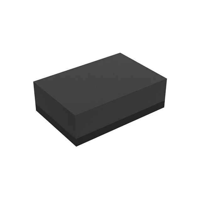
Most regulators use a reference and feedback loop. The loop measures the output, compares it with the reference and adjusts the pass element or switching action to correct an error. When a load switches on suddenly, the output capacitor supplies part of that immediate demand. The loop then corrects the remaining error within its response time.
Line regulation describes how steady-state output changes as input changes. Load regulation describes how steady-state output changes with load. A load transient is a separate test: check the size of the voltage dip or overshoot and how long recovery takes. These checks matter for rails with tight tolerances, even if the nominal voltage matches.
| Design question | Linear regulator | Switching regulator |
|---|---|---|
| Voltage conversion | Steps down | Buck steps down, boost steps up, and buck-boost can do both |
| Dominant loss or design concern | Heat from voltage drop and load current | Switching and conduction loss, layout and EMI |
| External parts | Usually input and output capacitors, plus feedback parts if adjustable | Typically an inductor, capacitors and sometimes additional parts |
| Where it fits | Small voltage drops or modest loads where simplicity or noise matters | Larger drops, battery-sensitive systems or higher-current rails |
Linear regulators suit small input-to-output drops, particularly on rails with modest current. A switching regulator suits larger drops and designs that need to step up or both step up and down. Compare complete circuit performance, including the switching stage layout, rather than the regulator IC alone.
Write down the input range at the actual pins, including sag and surge, and list the expected load peaks. Decide how much ripple and transient deviation the circuit can tolerate. For linear parts, check dropout over load and temperature, quiescent current, and the specified output capacitor range. For switching designs, check the inductor current rating, layout guidance, startup behavior and EMI constraints. A module may simplify layout, but its thermal and input-filter requirements still apply.
Use the low dropout ldo category to compare small-drop options, or compare dc dc voltage regulators for switching designs. The LDO selection guide covers dropout, noise and capacitor requirements in more detail.
Start with the rail, because the term voltage regulator also describes equipment used on utility distribution networks. This guide concerns DC power rails inside electronic equipment. For an embedded sensor board, write down the input range at the IC pins, the rail tolerance, the sleep current, the active peak and how long it lasts. A part that looks efficient at its rated current can waste more energy over a duty cycle spent mostly asleep.
Use this hypothetical comparison for a 3.3 V rail at 200 mA. The load needs 0.66 W. From a 12 V input, a linear regulator dissipates about 1.74 W before quiescent losses. A buck converter at an assumed 85% efficiency would draw about 0.78 W and lose about 0.12 W at the same load. That 85% is a design assumption. Replace it with the selected converter’s efficiency curve at the actual input and load before sizing the board. Linear and switching regulator design reference
A dual-stage design can make sense when the same 12 V input feeds a quiet analog rail. For a buck followed by an LDO, check that the lowest buck output, including ripple and sag, remains above the final output plus worst-case dropout. Then check rejection at the buck switching frequency. A power supply rejection figure measured at a much lower frequency cannot answer that question.
When a prototype fails only during a load step, compare the output dip and recovery time with the load’s limits. An average multimeter reading can look acceptable even while a short excursion resets a processor. Track voltage at the load as well as at the regulator so wiring and PCB drops are visible.
The classic 7805 is a fixed 5 V linear regulator. Follow the selected manufacturer’s datasheet for input headroom, bypassing and thermal limits. Some switching replacement modules use a compatible-looking pin arrangement, so confirm the actual device.
A conventional linear regulator is a step-down device. For a rail above its supply, choose an appropriate boost or other step-up topology and check startup and load limits.
Calculate heat first. A small input-to-output drop can make linear regulation practical even at appreciable current. At high current and a large drop, a switching design is usually easier to cool.
A passive divider sets a ratio. Its output changes as load changes. A regulated rail uses feedback to keep voltage within a defined tolerance across its operating range.
Compare worst-case input sag with required output plus dropout at the expected current and temperature. Add margin for the rail tolerance and the behavior of the upstream source.
For a ChipApex quote, send the input range, target output voltage, peak current, preferred package and order quantity.
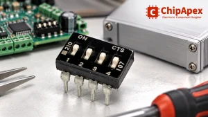
Choose a DIP switch by contact type, coded positions, footprint and signal ratings. Check logic polarity, assembly conditions and PCB configuration behavior.
View details
Learn how NAND flash works, its types (SLC, MLC, TLC), applications in SSDs & embedded systems, and how to source authentic, traceable ICs from trusted suppliers.
View details
Learn how optical sensing works, compare detection methods, and select sensors by target surface, ambient light, response time and electrical interface.
View details
Learn how to use ferrite beads for noise filtering. Check impedance, DC bias, placement, resonance and load-step behavior before selecting a part.
View details
The activity of extra discounts on wholesale prices is in full swing…
Please fill in your contact information and we will send you the latest wholesale price list.