 ChipApex | Global Electronic Components Supplier

SEARCH
Search Product
Search Post
— IC芯片 | 连接器 | 传感器 | 被动器件 —
Search productSearch post
— IC芯片 | 连接器 | 传感器 | 被动器件 —
The trend of science and technology is changing rapidly.
A throttle position sensor, or TPS, tells the engine controller how far the throttle plate has turned. The controller can compare that reading with the commanded angle and the driver’s pedal request. A fault code or poor acceleration can point to that signal chain, so check what the scan data actually shows before ordering a sensor.
The TPS measures position. The engine controller uses that information with pedal demand, airflow and other inputs to manage engine operation. In a cable-operated throttle, the cable moves the plate and the TPS reports where it went. In a drive-by-wire design, a motor moves the plate and the controller checks the resulting position against its command.
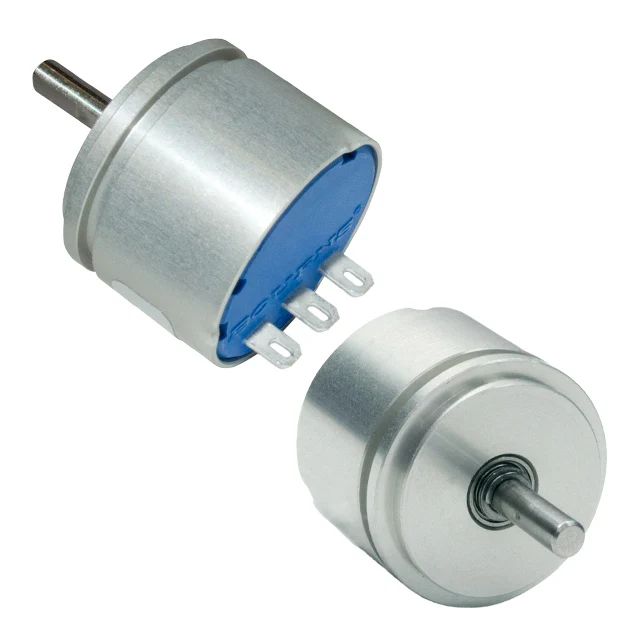
A potentiometric TPS has a resistive track and a wiper coupled to the throttle shaft. The controller reads the wiper voltage as the plate turns. Contacts can wear, especially in frequently used portions of travel. Intermittent dropouts may be easier to see in a recorded trace than on a single meter reading. The throttle potentiometer technical guide describes that construction and common failure modes.
A contactless position sensor measures a magnetic field associated with shaft rotation. The sensor and magnet geometry both affect the output, so the end-to-end transfer curve matters as much as package fit. The reading can come out as an analog signal or a digital interface depending on the device.
| Technology | How it reads position | Key integration check |
|---|---|---|
| Resistive potentiometer | Wiper moves along a track | Travel, contact wear, output loading and end points |
| Contactless magnetic sensor | Magnetic field changes with angle | Magnet alignment, air gap, transfer curve and interface |
| Redundant sensing channels | Two tracks or channels report related positions | Correlation requirements, diagnostics and vehicle specification |
Hesitation, an uneven idle or reduced-power mode can accompany an inconsistent throttle reading. They can also result from wiring, connector corrosion, supply or ground issues, a binding throttle mechanism, or another sensor fault. Read the diagnostic code and freeze-frame data, then compare pedal position, commanded throttle and actual throttle using the manufacturer’s diagnostic process. Repair decisions should follow the vehicle’s service instructions.
For component evaluation, compare ChipApex angle and linear position sensors by angle range, interface and mounting. Check the broader sensors and transducers catalog for other sensing functions used in the system.
TPS here means throttle position sensor. Catalog results for pressure or temperature sensors can use the same abbreviation, so start with the original application and part number. In a drive-by-wire throttle, compare pedal demand, commanded throttle angle and measured throttle angle. They represent different points in the control loop and need not read the same value. On a cable-operated design, the throttle is moved mechanically and the electrical sensor reports its position. Manufacturer overview of throttle sensor types
| Recorded observation | First question to investigate | Useful reference |
|---|---|---|
| Actual position drops out in the same region of travel | Is the signal interruption repeatable at that shaft angle? | Model-specific signal trace and wiring diagram |
| Both position channels move unexpectedly together | Do they share a supply, ground or connector path? | Vehicle circuit diagram and power supply checks |
| Command changes while actual position lags | Is the plate moving freely and is the actuator responding? | Manufacturer’s actuator and throttle body diagnostic procedure |
These observations narrow the next check. They do not identify a failed part on their own. A digital or redundant TPS may need scan data or a suitable capture tool. Start by identifying the interface and expected channel relationship in the service information. A generic voltage range found online is insufficient for approving a sensor.
For integrated throttle bodies, confirm whether the sensor is serviceable separately and whether the specified repair requires adaptation or a relearn. For component selection in a new design, ask for rotation range, shaft coupling or magnet geometry, output format, operating temperature and the required correlation between channels.
It is normally attached to or integrated into the throttle body near the throttle shaft. The accelerator pedal sensor is typically on the pedal assembly. Consult the vehicle documentation for the exact location and service procedure.
The plate turns with the throttle shaft. A wiper or contactless sensing element converts that rotation to a signal the controller can read. The controller uses the signal to track position and check that the throttle responds as expected.
No. Some analog sensors use a 5 V reference but operate over a narrower output range. Other devices use different interfaces. Verify the transfer curve, supply and pinout for the actual system.
They measure different mechanical points and are specified for different transfer functions. Match the assembly and its part number when sourcing a replacement.
Use the code to guide diagnosis. A connector, reference supply or wiring fault can produce a similar symptom. Follow the manufacturer’s test sequence before choosing the replacement.
For a ChipApex component inquiry, share the angle range, signal interface, temperature range, mechanical constraints, part number if known and quantity.
Learn how a TRIAC switches AC loads. Understand triggering, latching, holding current, phase control and thermal limits before choosing a component.
View details
Stop guessing which Op-Amp to use. We break down GBWP, Slew Rate, and Offset Voltage with real engineering insights. Find the right parts like NE5532DR & LM358DR at ChipApex.
View details
Choose a rocker switch by AC/DC ratings, contact arrangement, illumination, panel fit and sealing. Get practical checks for engineering and component sourcing.
View details
A comparator checks which of two input voltages is higher and changes its output state accordingly. It is useful when an analog signal must trigger a clear decision, such as an overvoltage warning or sensor threshold. Its input range, output type,...
View details
The activity of extra discounts on wholesale prices is in full swing…
Please fill in your contact information and we will send you the latest wholesale price list.