 ChipApex | Global Electronic Components Supplier

SEARCH
Search Product
Search Post
— IC芯片 | 连接器 | 传感器 | 被动器件 —
Search productSearch post
— IC芯片 | 连接器 | 传感器 | 被动器件 —
The trend of science and technology is changing rapidly.
A low-dropout regulator, or LDO, is a linear voltage regulator that maintains a lower output voltage with relatively little voltage difference between its input and output. It controls a pass device using feedback. Choosing an LDO requires checking dropout at the intended load, output accuracy, noise, capacitor requirements and heat dissipation.
LDOs are often useful for low-power rails or for post-regulating a switching supply. A small input-to-output difference can make them efficient, while a large voltage drop at high current can create substantial heat. Low dropout describes a headroom requirement, not a guarantee of low dissipation in every circuit.
The feedback network senses the output and compares it with an internal reference. An error amplifier adjusts the pass device to correct changes in supply or load. A fixed-output part sets the feedback ratio internally; an adjustable part uses a supported external network.
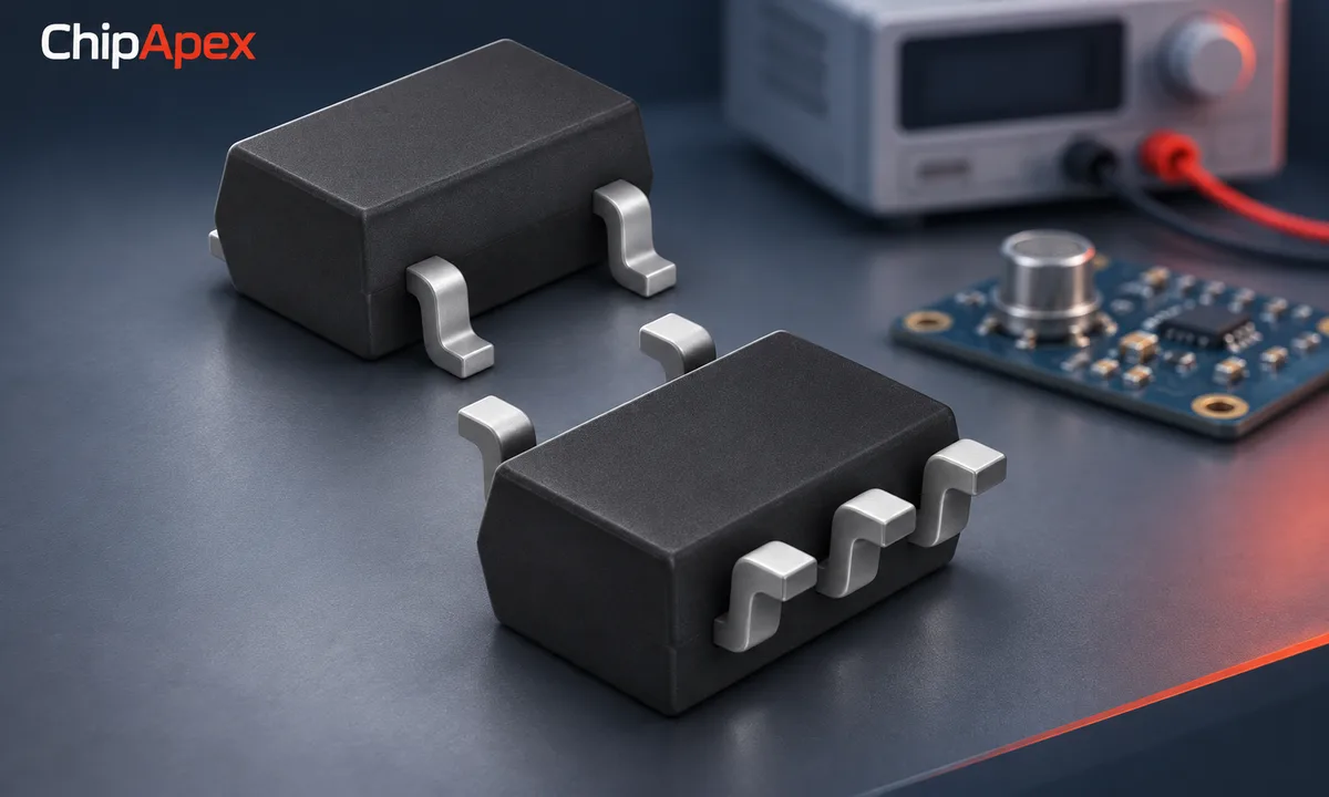
In a low dropout regulator circuit, the input supply still needs enough voltage to support the output and the required headroom. The device also has a minimum operating input voltage. These requirements can differ, especially in architectures that use a separate bias supply.
An LDO does not use an inductor-based switching stage to regulate the rail. That can simplify the external circuit, but noise from the regulator itself and disturbances arriving from the input remain design considerations. The ABLIC introduction and TI's regulator seminar in the sources describe this feedback arrangement.
Dropout is the input-to-output voltage difference at which the regulator can no longer maintain the specified regulation condition. Manufacturers define and test it using stated criteria. Compare those conditions before comparing two headline numbers.
As an illustrative check, a 3.3 V output requiring 0.2 V headroom at the intended load needs at least 3.5 V at its input for that dropout condition. Supply tolerance, cable loss, ripple and temperature may require additional allowance. This estimate does not override a higher minimum input-voltage requirement in the datasheet.
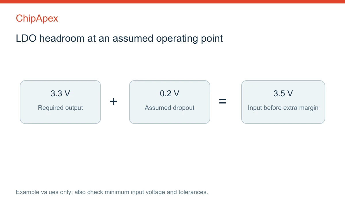
Read worst-case dropout at the relevant current and temperature. A typical low-current value can be misleading for a heavily loaded rail. Operating near dropout can also change ripple rejection and transient behavior before the output becomes obviously unusable. TI's dropout guidance explains why headroom and the pass-device architecture must be considered together.
For a first estimate, pass-device dissipation is approximately (VIN − VOUT) × IOUT. Ground-current consumption contributes additional input power. With an assumed 5 V input, 3.3 V output and 200 mA load, the first estimate is 0.34 W. At 12 V input with the same output and load, it rises to 1.74 W.
Ignoring ground current, efficiency is approximately VOUT/VIN: about 66% in the 5 V example and 27.5% in the 12 V example. These calculations describe assumed operating points, not measured product performance. The thermal resistance and board construction determine how much the junction temperature rises.
| Operating requirement | Useful starting point | What still needs checking |
|---|---|---|
| Small voltage drop and modest load | LDO | Dropout, stability and temperature |
| Large voltage drop or substantial power | Switching conversion | Ripple, layout, efficiency and transients |
| Sensitive rail after a switching stage | Switching supply followed by LDO | Headroom across ripple and PSRR at disturbance frequencies |
| Long battery standby time | Low ground-current regulator | Active current, shutdown leakage and operating mode |
If a dc dc converter supplies the LDO, check the minimum instantaneous voltage at the LDO input. Nominal voltage minus nominal dropout is not enough when the upstream rail has tolerance and ripple. Thermal shutdown should be a protection event, not the normal method of managing dissipation.
PSRR describes how input ripple transfers to the output under stated test conditions. It varies with frequency, load, headroom and external components. Output noise describes noise generated by the regulator, typically integrated over a specified frequency band. A high PSRR number does not establish low internal noise.
Select a high psrr ldo against the disturbance frequencies that reach the input. A specification at a low frequency may not predict attenuation of a switching fundamental or its harmonics. Check the curves at a comparable load and input-to-output difference.
Load-transient response describes the temporary output change when current demand changes. The control loop, output capacitor and interconnect all contribute. A sensor's analog front end may need a quiet supply during acquisition, while a digital device may create abrupt current steps. Evaluate the real operating pattern rather than only a constant-current bench load.
Use the capacitor range and ESR conditions specified for the exact regulator. Effective ceramic capacitance can fall with DC bias, so the printed capacitor value may overstate what the regulator sees. Extra output capacitance can also change startup time, inrush and discharge behavior.
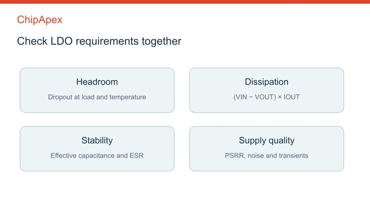
Some regulators need a minimum load for their specified behavior; others do not. Noise-reduction, soft-start and feedforward capacitors have different functions and should follow the device guidance. A circuit copied from a related family is not necessarily stable with a replacement part.
Review what happens if the input collapses while the output remains powered by a capacitor or another source. Reverse-current blocking is a device feature that must be verified. Also check enable thresholds, power-good behavior and sequencing requirements where several rails interact.
A conventional LDO regulates down from an input supply to a lower output. It cannot sustain an output above the available input by linear regulation. If the source can fall below the required rail, consider a suitable boost or buck-boost stage, with any LDO post-regulation chosen against the remaining headroom.
No. Low dropout helps when headroom is limited, but noise, ground current, stability, accuracy and thermal performance may be more important elsewhere. Compare dropout at the intended operating current and temperature. A favorable typical number at a light load does not establish the best complete design.
No. Ripple rejection depends on frequency and operating conditions, and layout can introduce paths around the regulator. Check PSRR at the relevant switching frequencies and headroom, then measure the assembled rail using an appropriate setup. The regulator also contributes its own output noise.
The voltage difference matters as much as the load current. Even a moderate current can produce considerable dissipation when the input is far above the output. Calculate the loss, include ground current where relevant, and assess the board's thermal path against the manufacturer's limits and derating guidance.
Only after reviewing pinout, input range, current, dropout, capacitor stability, enable logic and protection behavior. Reverse-current and startup characteristics may also differ. Output voltage alone does not establish compatibility, even when the package dimensions appear identical. Verify performance with the actual load and supply conditions.
Send ChipApex the input range, required output and tolerance, continuous and peak current, noise requirements, ambient temperature, capacitor constraints and package. Include an existing part number for replacements. These conditions make it possible to compare candidates against the rail rather than one dropout number.
Learn how DSPs (Digital Signal Processors) enable real-time audio, industrial motor control, 5G communications & medical imaging. Compare DSP vs MCU, choose fixed vs floating-point DSPs, and source authentic DSP chips at ChipApex.
View details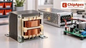
Select power transformers by input frequency, secondary VA, rectifier load, isolation, regulation and inrush. Build a clearer specification for your next RFQ.
View details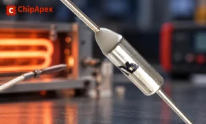
Understand thermal fuse operation, Tf, Th and Tm, electrical ratings and mounting. Check temperature limits and replacement requirements for your design.
View details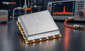
Understand voltage controlled oscillator tuning, phase noise and PLL operation. Check supply noise, output loading and requirements before selection.
View details
The activity of extra discounts on wholesale prices is in full swing…
Please fill in your contact information and we will send you the latest wholesale price list.

