 ChipApex | Global Electronic Components Supplier

SEARCH
Search Product
Search Post
— IC芯片 | 连接器 | 传感器 | 被动器件 —
Search productSearch post
— IC芯片 | 连接器 | 传感器 | 被动器件 —
The trend of science and technology is changing rapidly.
A solid-state relay (SSR) switches a load with semiconductor devices instead of moving contacts. Its input controls a separate output circuit, often through optical isolation. To choose an SSR, match the output to the AC or DC load, then check leakage, switching behavior, surge capability and heat dissipation under the actual operating conditions.
An SSR can be useful for frequent, quiet switching in a heater controller or equipment interface. Its suitability depends on the circuit. A device that fits an existing socket may have the wrong output technology, control requirements or thermal limits.
The input circuit receives a control signal and drives the output switching stage. In many designs a photocoupler transfers that signal across an isolation barrier. The load current flows through the output terminals, not through the controller's input connection. The exact barrier construction and ratings belong to the individual device.
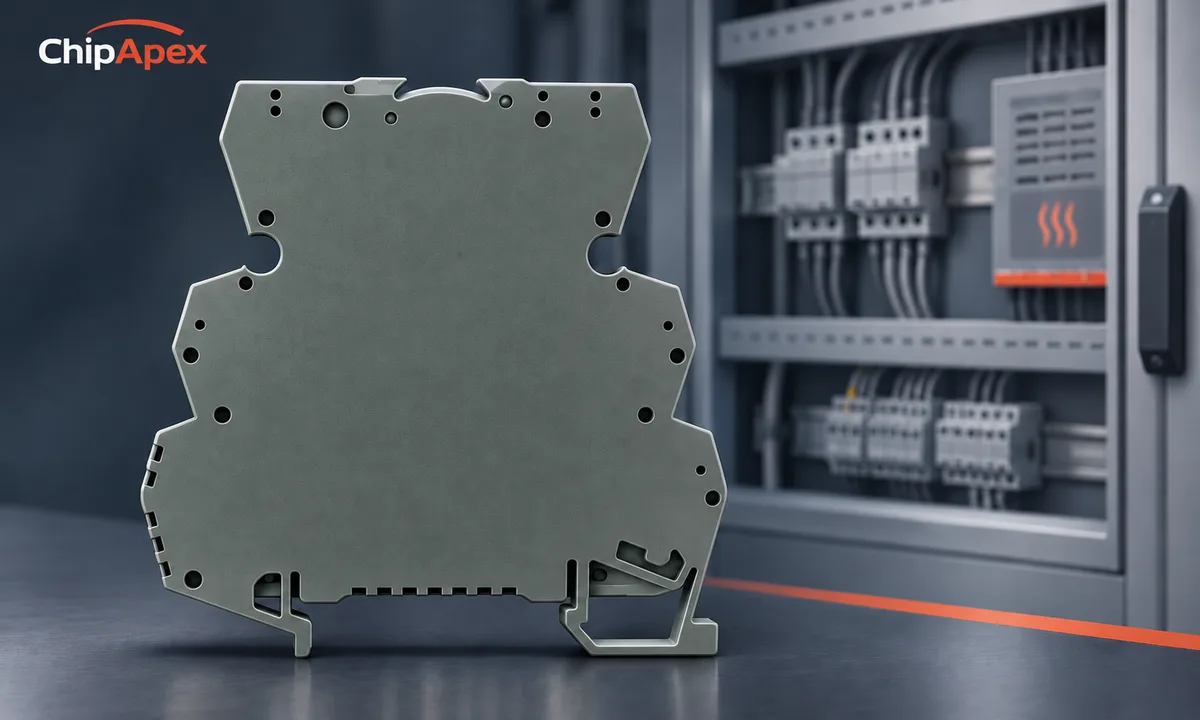
Compare solid state relays by output function before comparing current ratings. A semiconductor output has finite on-state loss and off-state leakage. Those characteristics explain several practical differences from electromechanical contacts, including heating while on and a small current through the load while off.
Other relays may be preferable when a circuit needs particular contact arrangements or very low off-state leakage. Conversely, mechanical contact wear and operating noise can matter in frequent switching. Choose against the required switching duty and load rather than assuming one relay technology is universally better. The OMRON overview in the sources explains the main operating arrangements.
The control-input label and load-output label describe different circuits. A DC control signal can operate an SSR intended to switch an AC load. That does not make the output suitable for a DC load.
| Output arrangement | Typical behavior | Selection consequence |
|---|---|---|
| Triac or thyristor AC output | Usually turns off when load current falls below its holding requirement | Check AC frequency, minimum load and commutation behavior |
| Transistor or MOSFET DC output | Switches a specified DC current path | Check polarity, blocking voltage and inductive-load protection |
| Back-to-back MOSFET arrangement | Some devices support AC and DC switching | Confirm the actual permitted load types and operating limits |
An AC-output device using triacs or thyristors may remain conducting on a DC supply after the control input is removed. The current has no normal AC zero crossing to help it turn off. This is a load-compatibility issue, not something a different input voltage will correct. OMRON addresses this directly in its AC-versus-DC FAQ.
For a replacement, record the complete input and output specifications from the original part. Include the wiring diagram and any polarity markings. Similar terminal counts do not establish functional equivalence.
A zero-cross SSR delays turn-on until the AC voltage is close to zero. That can reduce switching disturbance in suitable loads. A random-turn-on device responds without waiting for that voltage condition, within its specified response time. It can support control arrangements that need turn-on elsewhere in the cycle.
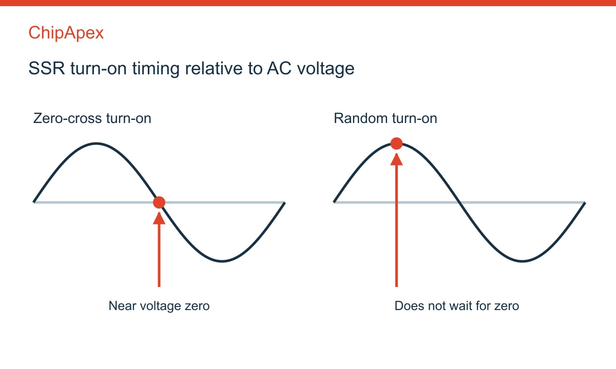
Phase-angle control requires a compatible output and controller. A zero-cross output cannot simply reproduce an arbitrary phase-angle command. For burst control, complete AC cycles can be switched in groups, but the control period and resulting load response still need review.
Treat turn-on and turn-off separately. In an AC semiconductor output, removing the input does not necessarily interrupt load current immediately. Inductive loads can shift the relationship between voltage and current, making commutation conditions important. Transformer and motor starting requirements also deserve their own assessment; a heater rating should not be transferred directly to those loads.
An SSR's off state is not an ideal open circuit. Semiconductor leakage and internal suppression networks can pass a small current. A high-impedance instrument may therefore show substantial voltage across an unloaded output, and a small electronic load may glow, chatter or fail to reset.
Check leakage at the specified supply voltage and temperature, along with the load's reset or release requirements. A minimum-load specification may also apply. A bleeder network can help in an appropriate design, but its resistance, continuous dissipation and electrical ratings must be calculated. It should not be added by copying an unrelated application example.
The same issue affects diagnostics. A voltage reading by itself does not establish how much current the output can deliver. Distinguish normal leakage, a wiring problem and a failed output using a measurement procedure appropriate to the equipment. OMRON's microload guidance provides examples of these interactions without making them universal ratings.
An SSR needs a thermal path sized for its actual loss. For an illustrative AC output with an approximately 1.6 V on-state drop at 8 A, conduction loss is roughly 12.8 W. This assumed calculation is not a rating for the pictured module. A MOSFET output instead may be estimated initially using current squared times on-resistance, with temperature and other losses included in a fuller analysis.
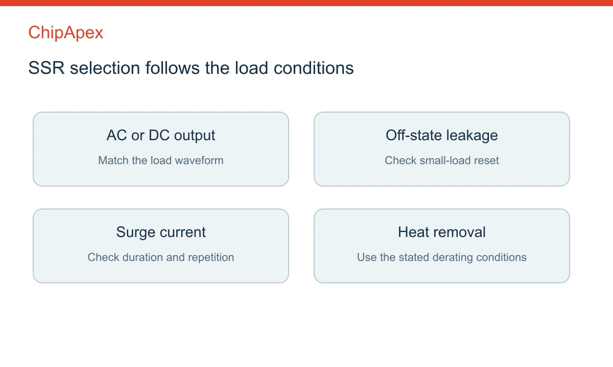
Read derating curves with the mounting orientation, ambient temperature and heatsink conditions. Interface material and fastening requirements can affect the thermal path. Closely spaced devices can heat one another inside a control cabinet even when each passed a bench test separately.
Separate repetitive operating current from short surge capability. A nonrepetitive surge rating does not describe an acceptable event on every switching cycle. Check load inrush, pulse duration and repetition against the manufacturer's data. Protective-device coordination also needs review for the actual prospective fault current.
SSRs can fail shorted, leaving the load energized. Where loss of control has a significant consequence, the system needs an appropriate independent means of interrupting power. Semiconductor off-state leakage and a control input set to zero should not be treated as a maintenance isolation boundary. This failure mode is specifically covered in OMRON's precautions.
Yes, if its output is designed and rated for that AC load. Input and output specifications are separate. Check the control voltage or current requirement on the input, then the load voltage, current, frequency and switching mode on the output. The input label alone does not identify load compatibility.
Off-state leakage or an internal suppression network may supply enough current to make a small LED load glow. Check the SSR's leakage specification and the load's behavior before concluding that the relay has failed. Some applications need a different output type or a properly designed load-side network.
No. Some integrate heat removal, and some low-loss devices can operate within their ratings without a separate heatsink. The decision follows the datasheet's thermal conditions and calculated loss. Package size or a large current label does not establish the permissible current in a sealed enclosure.
That depends on the motor and control method. A generic zero-cross relay should not be assumed suitable for speed control. Its turn-on timing, current-zero turn-off behavior and load ratings may not match the required drive. Use a control architecture designed for the specific motor and operating range.
Only after checking the full circuit. Differences include leakage, output voltage drop, polarity, contact arrangement, minimum load, thermal requirements and failure behavior. The controller must also satisfy the SSR's input requirements. A matching footprint or nominal current rating is not sufficient evidence of compatibility.
For a ChipApex inquiry, provide the input-control signal, AC or DC load voltage, continuous and startup current, switching frequency, ambient temperature and mounting space. Include the existing part number for replacements. These details help narrow the candidate components without assuming a nameplate current applies to every load.
Compare rheostat and potentiometer wiring and functions. Understand divider loading, wiper current, track power and practical component selection.
View details
Understand UART protocol framing, baud rate and electrical interfaces. Learn 8N1 timing, TX/RX wiring, buffering and practical troubleshooting steps.
View details
What is EEPROM? Learn byte-level storage, EEPROM vs Flash, I2C/SPI, BOM selection & sourcing risks. Authentic EEPROMs at ChipApex.
View details
Compare thermistors, RTDs, thermocouples and temperature ICs. Learn how range, accuracy, response, interfaces and mounting affect component selection.
View details
The activity of extra discounts on wholesale prices is in full swing…
Please fill in your contact information and we will send you the latest wholesale price list.

