 ChipApex | Global Electronic Components Supplier

SEARCH
Search Product
Search Post
— IC芯片 | 连接器 | 传感器 | 被动器件 —
Search productSearch post
— IC芯片 | 连接器 | 传感器 | 被动器件 —
The trend of science and technology is changing rapidly.
A pin header is a connector with exposed male contacts arranged in one or more rows, usually held by an insulating housing. It connects a PCB to another board, socket or cable assembly. Choosing one requires more than counting pins: pitch, contact geometry, mating length and electrical conditions must all match.
When selecting a connector header, identify its intended mating part first. Two connectors can share a pitch and still be mechanically or electrically incompatible.
Pin headers appear in board-to-board links, programming ports, removable modules and wire-to-board connections. They may be unshrouded, partially shrouded or fully enclosed. Straight and right-angle versions change the direction of the mating interface and the space required around it.
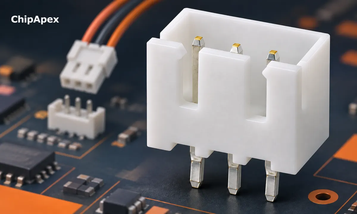
A shroud can help alignment and may provide polarization, but the actual keying arrangement must be checked. A friction-fit connection and a latched connection also behave differently under vibration or cable load. Housing color does not establish compatibility.
For a field-service connection, consider insertion access, identification and accidental reversal. For an internal assembly, prioritize the full tolerance stack and assembly sequence. A connector that fits on the drawing can still be difficult to mate once the enclosure is installed.
Pitch is the center-to-center spacing between adjacent contacts. Common examples include 2.54 mm, 2.00 mm and 1.27 mm, but many other series exist. Do not round a measurement to the nearest familiar value without checking the drawing.
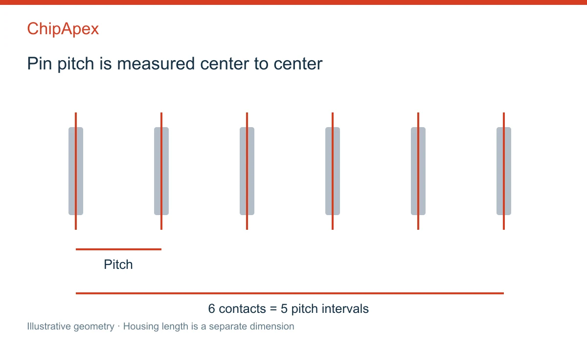
For a straight row with N contacts, the center-to-center span from the first to the last is (N − 1) × pitch. A ten-position row at 2.54 mm pitch therefore spans 22.86 mm between the first and last contact centers. The housing's total length will be different.
Measure across several intervals when practical, then divide by the number of intervals. This reduces the effect of a small single-gap measurement error. For two-row connectors, verify row-to-row spacing separately. It need not equal the pitch along each row.
Pin numbering also needs a drawing. Some connectors use alternating odd and even numbers across rows; other arrangements differ. Establish the viewing direction, pin-one mark and mating orientation before creating a footprint or cable pinout.
| Detail | Why it matters |
|---|---|
| Contact cross-section | Must fit the socket contact design |
| Exposed mating length | Determines engagement and interference |
| Housing and polarization | Control alignment and permitted orientation |
| Board stack height | Must fit both connector halves and tolerances |
| Tail length | Must suit PCB thickness and soldering process |
| Right-angle offset | Affects enclosure and edge clearance |
Do not use the overall pin length as the mating length. Part of the contact may be inside the housing or below the PCB. A long post can bottom out in a socket; a short one may make unreliable contact.
Manufacturer configured header specifications show how pitch, post length, plating, row count and termination are encoded as distinct options. Use the exact configured drawing and approved mating part for the component being sourced.
A per-contact current rating is measured under stated conditions. Ambient temperature, number of powered contacts, wire size, PCB copper and allowable temperature rise can change the usable current. Do not multiply a headline per-pin rating by the number of contacts and assume the whole connector can carry that total continuously.
Contact resistance produces heat according to I²R. Poor engagement, contamination or a damaged contact can raise resistance and temperature. Ratings should be evaluated for the complete mated pair, not only the male header.
Parallel contacts require particular care. Small differences in resistance can create unequal current sharing. Unless the connector documentation supports the intended arrangement, paralleling pins is not a reliable shortcut to a higher current rating.
For a power connection, voltage rating and insulation spacing matter alongside current. For fast signals, signal integrity and return-path layout may matter before the nominal current rating becomes relevant.
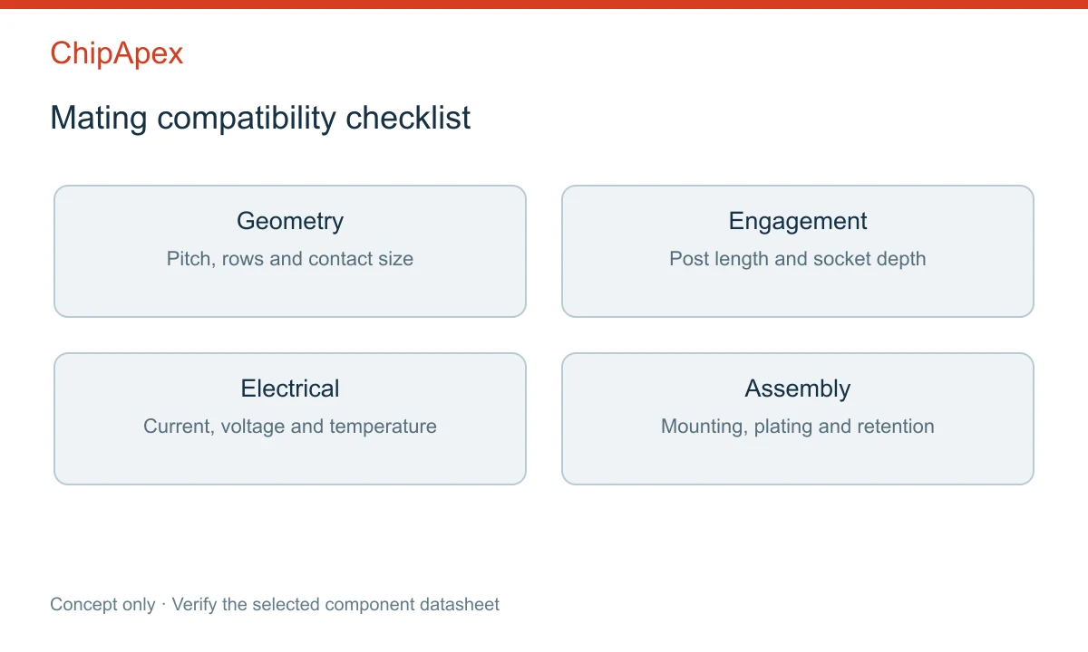
Plating affects wear, contact behavior and suitability for the expected environment. Gold thickness, tin finish and the mating contact finish are specific parameters, not simply cosmetic choices. Follow the connector manufacturer's mating recommendations and cycle-life conditions.
Through-hole headers can provide useful mechanical anchoring, while surface-mount headers support particular assembly processes and board layouts. Neither is automatically better for every product. Retention features, solder joints, board support and applied cable force determine the mechanical result.
Check reflow or wave-solder requirements, coplanarity, pick-and-place features and packaging. If the connector is repeatedly unplugged, verify the specified mating cycles and handling procedure. Use strain relief where cable forces would otherwise reach the contacts or solder joints.
An interface to current sensors may need careful separation of power and low-level signal paths. A control board containing shift registers needs a reliable logic return and clear pin assignment. The connector does not define the communication or electrical interface by itself.
For a ChipApex quotation, send the part number, mating part, pitch, rows, positions, orientation, termination, plating, mating length and quantity. Include a drawing for legacy replacements. State the application current and environmental conditions when alternatives are being considered.
No. Pitch is only one dimension. Contact shape, mating length, housing, row spacing and approved mating parts can differ.
A pin header normally refers to male contacts. A female socket or receptacle is a mating component with its own geometry and ratings.
Some breakaway series permit this, while others do not. Check the product construction and ensure the resulting edge and remaining contacts meet the application requirements.
Insufficient engagement, incompatible contact geometry, contamination, wear or mechanical stress can cause intermittent behavior. Physical insertion alone is not proof of correct mating.
No. The height depends on both connector halves, post and socket geometry, board placement and tolerances. Use the complete assembly drawing.
Choose an AC to DC converter by input range, output demand, isolation, efficiency and thermal derating. Compare architectures and check installation needs.
View details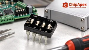
Choose a DIP switch by contact type, coded positions, footprint and signal ratings. Check logic polarity, assembly conditions and PCB configuration behavior.
View details
Learn what an integrated circuit is, how ICs work, the main types and the specs to check before choosing a part for your design with ChipApex.
View details
Practical MCU selection guide for engineers: compare STM32, ESP32 & NXP, avoid counterfeits, and ensure supply chain reliability. Authored by ChipApex FAE.
View details
The activity of extra discounts on wholesale prices is in full swing…
Please fill in your contact information and we will send you the latest wholesale price list.

