 ChipApex | Global Electronic Components Supplier

SEARCH
Search Product
Search Post
— IC芯片 | 连接器 | 传感器 | 被动器件 —
Search productSearch post
— IC芯片 | 连接器 | 传感器 | 被动器件 —
The trend of science and technology is changing rapidly.
Current sensors convert current into a signal that a control or measurement circuit can use. The right method depends on whether the current is AC, DC or both, how quickly it changes, and whether galvanic isolation is required. Range alone is not enough to choose a sensor.
For motor drives, power supplies and battery systems, compare current sensors against the waveform and fault conditions. A device that measures steady current accurately may be too slow for protection or may recover poorly after an overload.
A sensing system may measure a conductor's magnetic field or the voltage across a known resistance. Its output can support energy monitoring, current regulation, load diagnostics or overcurrent detection. These functions place different demands on accuracy, bandwidth and response time.
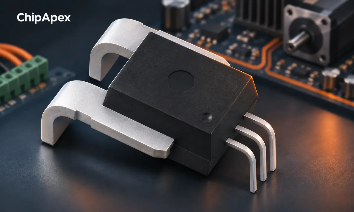
Define continuous current, peak current, pulse duration, direction and expected fault current. Include the required measurement at light load. A sensor with a large full-scale range may have too much offset or noise to resolve the smallest current of interest.
Also specify where the measurement occurs. A low-side shunt changes the ground path. A high-side shunt must tolerate the circuit's common-mode voltage and transients. Magnetic sensing avoids some insertion issues but introduces its own offset, field and isolation constraints.
| Method | AC/DC capability | Main tradeoff |
|---|---|---|
| Shunt plus amplifier | DC and AC within system bandwidth | Dissipation and common-mode requirements |
| Hall-effect sensor | DC and AC within rated bandwidth | Offset, drift, magnetic interference and isolation rating |
| Current transformer | AC; cannot measure steady DC | Low-frequency response, burden and saturation |
| Rogowski coil | Changing current; requires integration | Flexible range, integrator accuracy and low-frequency limits |
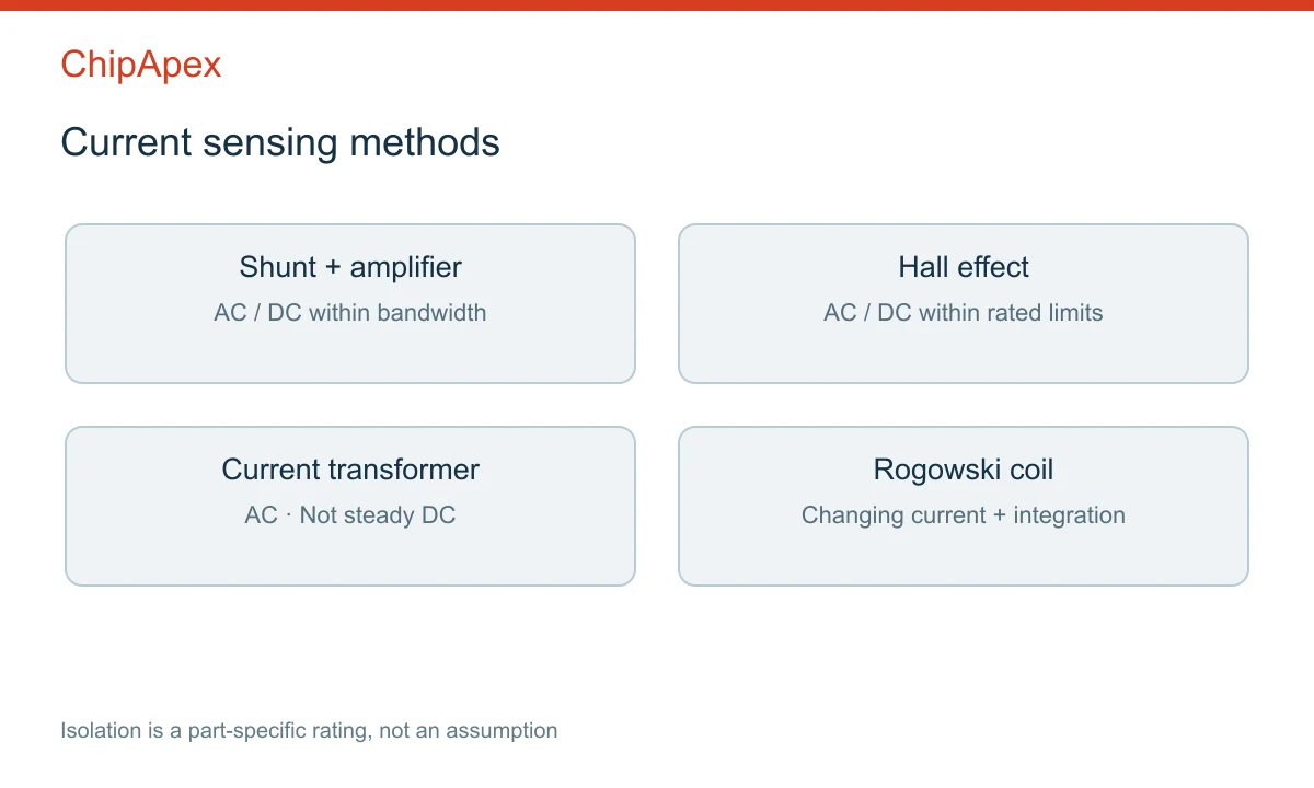
A current transformer depends on changing magnetic flux. It does not provide a sustained output proportional to steady DC. DC in the primary can also bias the core and impair AC measurement. Evaluate ct current sensors only where the waveform and frequency range are appropriate.
A Rogowski coil produces a signal related to the rate of change of current. An integrator reconstructs the current waveform over the designed bandwidth. It is useful for some high-current and transient applications, but it is not a direct substitute for a DC Hall sensor.
Open-loop and closed-loop magnetic sensors also differ. Feedback-based designs can improve some performance characteristics at the cost of power, size or complexity. The manufacturer's current-sensing comparison provides a useful overview of architecture tradeoffs.
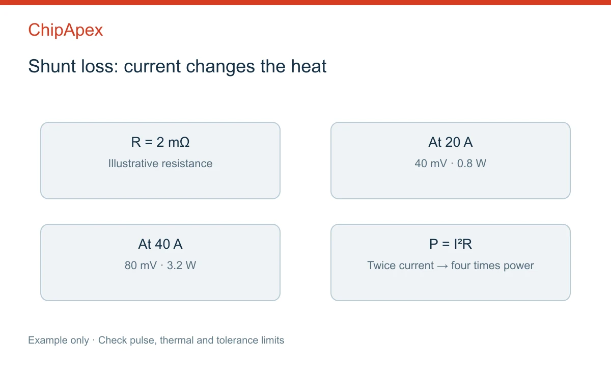
For a shunt resistor, voltage is V = I × R and dissipation is P = I² × R. Increasing resistance creates a larger measurement signal but also increases voltage drop and heat.
As an illustrative calculation, a 2 mΩ shunt carrying 20 A produces 40 mV and dissipates 0.8 W. At 40 A, dissipation becomes 3.2 W. These values exclude tolerance, temperature coefficient and layout effects; they are not a component rating recommendation.
Check continuous and pulse ratings, thermal conditions and Kelvin connections. Sense traces should measure the intended resistor terminals rather than including uncontrolled copper and joint resistance. The amplifier must accommodate input common-mode voltage, offset, gain error and the required output swing.
An instrumentation op amp may suit some measurement circuits, but a general-purpose instrumentation amplifier is not automatically a high-side current-sense amplifier. Verify its input range and transient behavior before considering it for that role.
Bandwidth describes frequency response; it does not fully specify the delay from a fault to a protective action. Sensor response, filtering, ADC sampling, digital processing and output logic all contribute to total latency.
In a switching power circuit, reject unwanted switching artifacts without filtering away the current information needed for control. PWM common-mode transients can disturb shunt amplifiers. Magnetic sensors can be affected by nearby conductors, external fields and mechanical placement.
If an adc converter samples the output, coordinate the acquisition timing with the waveform and control cycle. Include anti-aliasing and settling requirements. Oversampling a slow sensor does not recover a faster signal that the sensor has already attenuated.
Galvanic isolation is a part-specific property with defined working voltage, insulation construction and test conditions. Magnetic operation alone does not establish a usable safety isolation rating. PCB spacing and the rest of the system must also satisfy the application requirements.
Budget offset, sensitivity error, nonlinearity and temperature drift. Zero-current calibration can reduce a stable offset, but it may not correct drift under changing temperature or an external magnetic field. Check behavior after overload and power cycling.
For a current transformer, follow the manufacturer's burden and secondary-circuit instructions. Opening the secondary while primary current flows can produce hazardous voltage in applicable CT designs. The burden also affects accuracy, frequency response and saturation margin.
Send ChipApex the preferred part number, AC/DC waveform, continuous and peak current, required bandwidth, isolation requirements, supply, output type, package and quantity. Include the mechanical arrangement when the conductor passes through an aperture or the sensor mounts to a busbar.
Use manufacturer current sensor documentation to distinguish the available measurement architectures, then validate the chosen model under the actual thermal and electrical conditions. A substitution should preserve the required behavior, not merely the measurement range.
Not steady DC. Use a suitable DC-capable method such as a shunt-based system or an appropriately rated magnetic sensor.
No. Accuracy depends on the full error budget, temperature, calibration and operating conditions. Each method has strengths and limitations.
Possible causes include offset, noise, external magnetic fields, leakage current or a grounding problem. Compare the reading with a controlled zero-current condition.
Sometimes, but its response time and fault output must satisfy the protection requirement. A slow, highly filtered measurement channel may be unsuitable for fast shutdown.
Check range, waveform capability, isolation, sensitivity, offset, bandwidth, output interface and pinout. Matching the supply voltage and package is not sufficient.
A positive temperature coefficient (PTC) thermistor is a resistor whose resistance rises as its temperature rises. Depending on its material and curve, that change can be gradual or very steep around a transition temperature. Designers use PTC par...
View details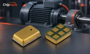
Choose a vibration sensor for machine monitoring. Compare sensing methods, bandwidth, noise and mounting, then define the signal-chain requirements.
View details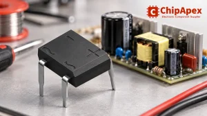
Select a bridge rectifier by reverse voltage, capacitor charging current, startup surge and cooling. Work through a stated DC voltage and ripple example.
View details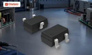
Learn how a diode conducts, how to identify anode and cathode, and when to choose rectifier, TVS, Zener or photodiode types for a circuit.
View details
The activity of extra discounts on wholesale prices is in full swing…
Please fill in your contact information and we will send you the latest wholesale price list.

