 ChipApex | Global Electronic Components Supplier

SEARCH
Search Product
Search Post
— IC芯片 | 连接器 | 传感器 | 被动器件 —
Search productSearch post
— IC芯片 | 连接器 | 传感器 | 被动器件 —
The trend of science and technology is changing rapidly.
An insulated-gate bipolar transistor, or IGBT, is a power switching device with a voltage-controlled gate and a bipolar conduction mechanism. It is used in applications such as motor drives and power converters. Selecting one requires checking conduction loss, switching energy, gate drive and protection at the circuit’s operating conditions.
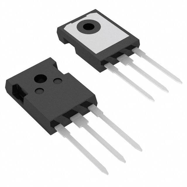
The gate controls whether current can flow between collector and emitter. The device needs a gate drive referenced to its emitter. Charging and discharging the gate takes current even though the gate is insulated from the conduction path.
During turn-on and turn-off, collector voltage and current overlap. That overlap creates switching loss. Stored charge also influences turn-off behavior. The datasheet specifies switching energy under particular voltage, current, gate resistance and temperature conditions. Treat those conditions as part of the value.
A single IGBT package and an IGBT module can serve different mechanical and circuit arrangements. A module may contain several switches, diodes or additional functions. Confirm the internal circuit before assigning a replacement. ChipApex lists IGBTs, single IGBTs and IGBT modules as separate categories.
For a MOSFET, conduction loss is often estimated from current squared times on-resistance at the relevant temperature. For an IGBT, a first-pass estimate uses collector current and the corresponding collector-emitter saturation voltage. Both devices also have switching losses. Their relative advantage depends on the actual current waveform, voltage, frequency and thermal conditions.
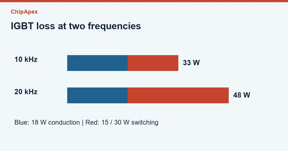
Assume a hypothetical IGBT carries a flat 20 A for half of each cycle. If its on-state drop is treated as 1.8 V, average conduction loss is approximately 1.8 × 20 × 0.5 = 18 W. If turn-on plus turn-off energy at the relevant test point is 1.5 mJ, switching at 10 kHz gives another 15 W. The initial total is 33 W per device, before additional losses and system effects.
At 20 kHz with the same assumed switching energy, the switching contribution becomes 30 W and the initial total becomes 48 W. That comparison shows why increasing frequency can change the thermal requirement. These numbers are illustrative. For a real motor inverter, integrate losses over the current waveform and interpolate only as supported by the manufacturer’s model.
| Datasheet item | Check it against |
|---|---|
| Collector-emitter voltage rating | Bus voltage, overshoot and required design margin |
| Saturation-voltage curves | Current, gate voltage and junction temperature |
| Turn-on and turn-off energy | Test voltage, current, gate resistor and commutation conditions |
| Thermal data | Package, interface material, cooling and duty cycle |
| Safe operating limits | Switching trajectory and fault-protection behavior |
The IKW25N120CS7 datasheet provides one example of these condition-dependent curves. Do not apply its values to a different IGBT solely because the voltage rating is similar.
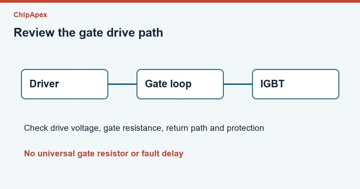
The gate driver must charge the device quickly enough for the switching target while keeping overshoot, ringing and electromagnetic interference within the design limits. Check its drive voltage, peak current, isolation requirements and undervoltage behavior. The gate-emitter absolute maximum rating is a stress limit, so the intended drive should follow the recommended operating conditions.
Changing gate resistance changes switching speed and can change switching energy. Reducing it indiscriminately can increase voltage overshoot or unwanted turn-on through coupling. Driver layout, emitter return and loop inductance therefore belong in the device selection review.
For short-circuit protection, use the selected device’s stated withstand conditions if provided and the complete detection-plus-turn-off time. A generic protection delay cannot establish suitability for every IGBT. Check the peak junction temperature and transient thermal impedance for both normal duty and abnormal events. Manufacturer switching models and application notes can help estimate the operating point. Infineon IGBT technical resources
It stands for insulated-gate bipolar transistor. It combines gate-controlled operation with bipolar conduction characteristics. The name identifies a device family. It does not establish a universal switching frequency, voltage drop or gate voltage, all of which must be checked for the selected part.
The choice depends on the operating point and circuit topology. Compare conduction and switching loss at temperature, then consider reverse-current behavior, gate drive and cooling. A general voltage boundary cannot replace an evaluation using the actual candidates and load waveform.
It controls gate charge and discharge relative to the emitter. It may also provide isolation, undervoltage lockout and protection functions. Confirm which features are actually present and whether their timing and drive ratings match the IGBT and the circuit.
No. Some packages or modules include an antiparallel diode and others require a separate device. Check the internal circuit diagram and the diode’s ratings. The reverse-current path affects commutation and switching loss as well as the bill of materials.
Only after checking the other specifications. Gate charge, switching energy, capacitance, package layout and protection behavior can change. A larger current rating can place a different demand on the driver and cooling, so it is insufficient as the sole replacement criterion.
For a ChipApex quote, provide the original device, bus voltage, current waveform, switching frequency, driver supply, package and quantity.
Learn how a diode conducts, how to identify anode and cathode, and when to choose rectifier, TVS, Zener or photodiode types for a circuit.
View details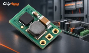
Select a DC-DC converter by input range, topology, isolation and temperature. Compare ripple, efficiency and load limits before choosing a component.
View details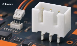
Choose a pin header by pitch, mating geometry, current rating and mounting. Learn why matching pin count and spacing does not guarantee compatibility.
View details
Learn how optical sensing works, compare detection methods, and select sensors by target surface, ambient light, response time and electrical interface.
View details
The activity of extra discounts on wholesale prices is in full swing…
Please fill in your contact information and we will send you the latest wholesale price list.