 ChipApex | Global Electronic Components Supplier

SEARCH
Search Product
Search Post
— IC芯片 | 连接器 | 传感器 | 被动器件 —
Search productSearch post
— IC芯片 | 连接器 | 传感器 | 被动器件 —
The trend of science and technology is changing rapidly.
“Spade connector” can mean a fork terminal secured under a screw, or a flat-tab quick-disconnect connection in workshop usage. These are different mating systems. Identify the connection first, then match its mechanical dimensions, conductor range, insulation and crimp tooling. A color or nominal width alone cannot establish a suitable replacement.
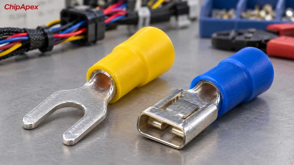
A fork terminal has an open tongue that fits around a screw or stud. It can often be fitted without removing the fastener completely. A ring terminal fully surrounds the stud and has different retention behavior. Follow the equipment specification when choosing the tongue style.
A quick disconnect uses a tab and a receptacle. The tab is the projecting blade and the receptacle slides over it. In this family, “male” and “female” refer to the mating contact, while insulation or locking features may add other dimensions. A fork terminal is not the male half of a quick-disconnect pair.
| Connection | Mating dimension to identify | Typical drawing details |
|---|---|---|
| Fork or spade tongue | Screw or stud opening | Tongue width, slot width and barrel clearance |
| Male tab | Tab width and thickness | Length, retention feature and contact finish |
| Female receptacle | Compatible tab dimensions | Insertion depth, housing and retention |
| Conductor crimp barrel | Specified wire range | Conductor area, insulation diameter and strip length |
The TE PIDG terminal guide and FASTON terminal catalog show how fork terminals and tab/receptacle systems are specified separately.
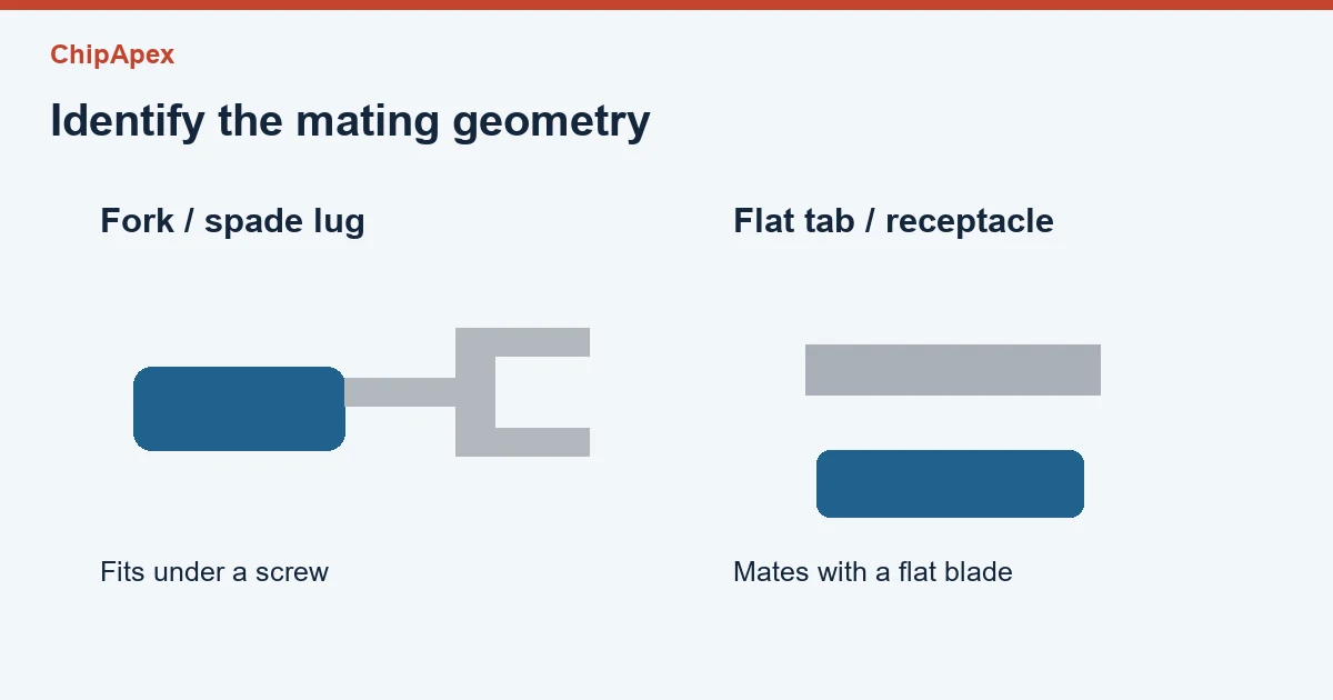
For a fork terminal, compare the actual opening with the manufacturer’s stud-size designation. Check the overall tongue width against nearby terminals or barriers. A tongue that reaches the screw can still collide with an adjacent pole or sit poorly under the intended clamping surface.
For a quick-disconnect receptacle, match both tab width and thickness. A nominal 6.3 mm tab width is about 0.248 inch, commonly described as 0.250 inch. That conversion identifies the width family only. Two parts can have the same width and different thickness requirements, spring forces or retention features.
The conductor range is a third check. It describes the wire intended for the crimp barrel and may be given in AWG or square millimeters. The insulation support also has a diameter range. Do not force a large insulated wire into a barrel because the copper cross-section seems close enough. Use the terminal’s stated conductor construction and insulation requirements.
Color coding can help distinguish parts within a documented series. Across suppliers, insulation systems and uninsulated products, the drawing and wire specification provide the more reliable identification.
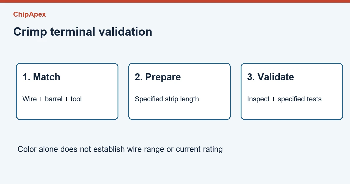
A terminal, die and wire form one termination system. Use the manufacturer’s specified tooling or a qualified process covering the combination. A generic tool that closes the barrel can still produce a crimp outside the permitted height or shape.
Before crimping, verify the strip length and avoid damaged or missing strands. After crimping, inspect the conductor location, insulation support and any exposed strands. The assembly process may specify crimp-height checks, pull testing or other validation. Use its test method and acceptance criteria. There is no single universal pull force for every spade terminal.
| RFQ detail | Why it prevents a mismatch |
|---|---|
| Fork, ring, tab or receptacle | Establishes the connection family |
| Stud opening or tab width and thickness | Establishes the mechanical interface |
| Wire range and insulation diameter | Matches the crimp barrel and support |
| Current, temperature and installation environment | Defines the electrical and material requirements |
| Part number and drawing | Resolves supplier-specific dimensions and tooling |
ChipApex’s connector catalog is a starting point for related interconnect sourcing. Include the mating component as well as the terminal when requesting a match. A claim that a connector fits should be backed by the dimensions and termination requirements of both parts.
The names can describe different hardware. A fork terminal goes around a screw or stud. A female quick-disconnect receptacle mates with a blade tab. A photo of the contact end and a dimensioned drawing make the distinction clear when sourcing from a new supplier.
Use color as a cue within a known product family, then confirm the wire range and dimensions. Colors alone do not identify the contact finish, stud opening, tab thickness, temperature rating or approved tooling. An uninsulated terminal may have the same mating geometry with a different termination process.
The width is only one dimension. Check the specified tab thickness, insertion length and locking arrangement. A connection that feels tight during one assembly trial does not establish compatibility over the service temperature, vibration or expected mating cycles.
Follow the terminal and assembly specification. Adding solder changes the termination, can wick into the wire and affects flexibility near the joint. It can also make an otherwise qualified crimp process different from the one originally validated. Use the documented process for the chosen terminal.
Possible causes include excessive current, poor contact engagement, a damaged receptacle or a defective termination. Confirm the load and inspect the complete current path using the equipment’s service procedure. Replacing the insulation color or fitting a larger-looking terminal does not resolve the cause by itself.
For a ChipApex inquiry, send the terminal drawing or photos, mating dimensions, wire size, environmental conditions and target quantity.

Practical MCU selection guide for engineers: compare STM32, ESP32 & NXP, avoid counterfeits, and ensure supply chain reliability. Authored by ChipApex FAE.
View details
Choose a vibration sensor for machine monitoring. Compare sensing methods, bandwidth, noise and mounting, then define the signal-chain requirements.
View details
A comparator checks which of two input voltages is higher and changes its output state accordingly. It is useful when an analog signal must trigger a clear decision, such as an overvoltage warning or sensor threshold. Its input range, output type,...
View details
Understand load cell sensor output, bridge wiring and calibration. Learn how mV/V sensitivity, mechanics and ADC noise affect measurement accuracy.
View details
The activity of extra discounts on wholesale prices is in full swing…
Please fill in your contact information and we will send you the latest wholesale price list.