 ChipApex | Global Electronic Components Supplier

SEARCH
Search Product
Search Post
— IC芯片 | 连接器 | 传感器 | 被动器件 —
Search productSearch post
— IC芯片 | 连接器 | 传感器 | 被动器件 —
The trend of science and technology is changing rapidly.
An automotive relay uses a small control current to operate contacts in a separate load circuit. It lets a switch or control module command a fan, pump or other load without carrying that load current through the control wiring. The correct relay depends on the coil supply, contact arrangement, load behavior and operating environment.
A replacement that fits the socket can still be electrically wrong. Before comparing auto relays, identify the original terminal diagram and the actual load, including startup current. A current number printed on the case does not describe every switching condition.
In an electromechanical relay, current through a coil produces a magnetic field. That field moves an armature, changing the contact state. When coil current disappears, a spring normally returns the contacts to their unpowered position. The coil and contact circuits have different jobs and separate ratings.
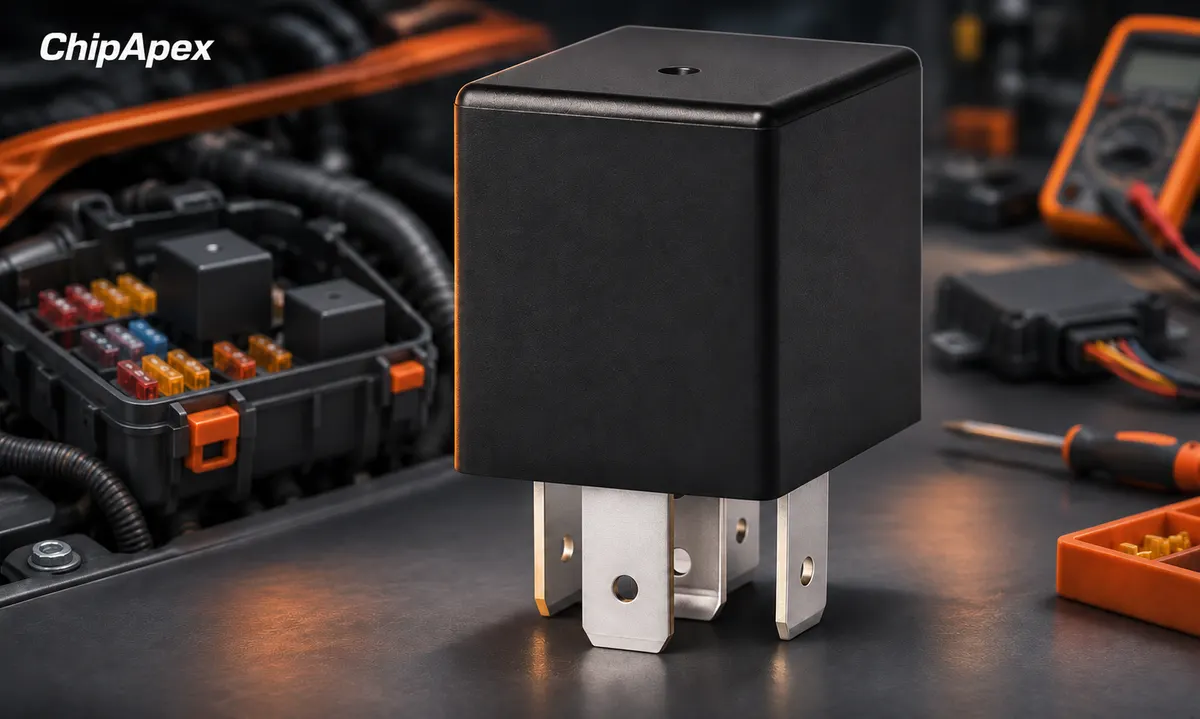
The coil may draw much less current than the load, but a controller output must still be designed to drive it. A transistor driver, protective components and suitable wiring may be required. Contact isolation also has limits: a relay is not automatically suitable for every voltage just because its control and load paths are separate.
Typical applications include cooling fans, auxiliary lighting, pumps and heaters. Each places different stress on the contacts. A lamp filament can draw a large cold-start current; a motor can draw substantial startup or stall current; an inductive load produces a transient when interrupted.
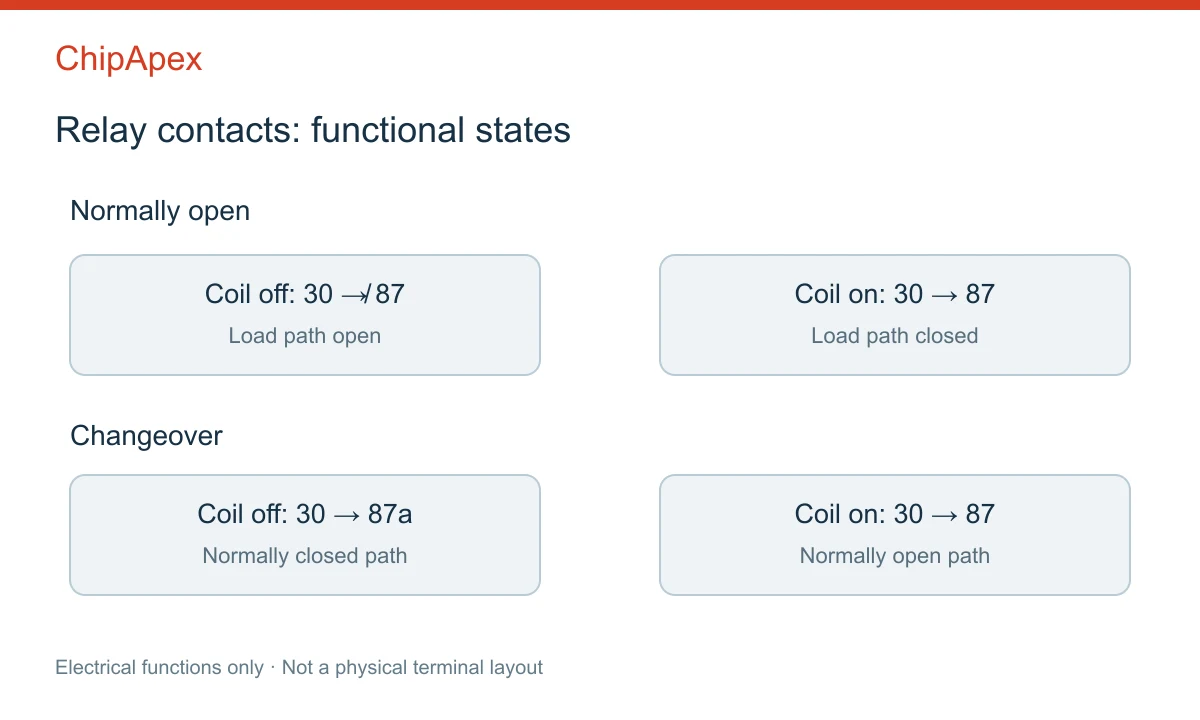
These labels are common on automotive relays, but the device diagram remains the authority. They describe electrical functions, not a universal physical pin position.
| Common label | Typical function | Check before installation |
|---|---|---|
| 85 and 86 | Coil connections | Coil voltage and suppression polarity |
| 30 | Common load contact | Supply path and wiring rating |
| 87 | Normally open contact | Connected to common when energized |
| 87a | Normally closed contact | Connected to common when unpowered |
Some five-terminal parts have two normally open outputs rather than one normally open and one normally closed output. They are not interchangeable with changeover relays merely because the terminals fit.
A diode-suppressed coil has a required polarity. Reversing its supply may forward-bias the diode and cause a fault. A resistor-suppressed coil behaves differently. Check the symbol and datasheet rather than assuming that either coil terminal can always connect to positive.
Separate continuous carrying current from the current the relay can make and break. Contacts may carry a current under one condition but have a lower switching capability for a particular load. Voltage, load type, ambient temperature and required service life all matter.
For a motor, record normal running current, startup duration and fault or stall behavior. For a capacitive input, establish inrush current. For a heater, assess cold resistance and cycling frequency. These details help identify a suitable auto relay more reliably than matching a headline amperage.
A fuse protects against defined overcurrent conditions; it does not make an underrated relay acceptable. Socket terminals, crimps, conductor size and contact resistance also affect temperature. A good relay can still overheat in a damaged or poorly assembled socket.
Consider a hypothetical 10 A running load with a brief 40 A startup peak. That does not automatically require a relay labeled “40 A,” nor prove that such a relay is sufficient. The startup duration, repetition, voltage and manufacturer's load-specific limits decide the answer. This example illustrates the specification process, not a recommended rating.
Interrupting coil current creates a voltage transient. Suppression limits that transient, but the chosen circuit also affects how quickly the magnetic field collapses and the contacts release. A simple diode can slow release compared with other clamp arrangements. That change can influence contact behavior under load.
The manufacturer's coil-suppression guide explains why protection and switching dynamics need to be considered together. Follow the relay and driver requirements instead of adding a generic diode to every circuit.
Keep coil suppression separate from load suppression in the design review. Protecting the coil driver does not necessarily control the transient produced by a motor or another inductive load. Likewise, an existing vehicle control module may expect a particular coil resistance or diagnostic response.
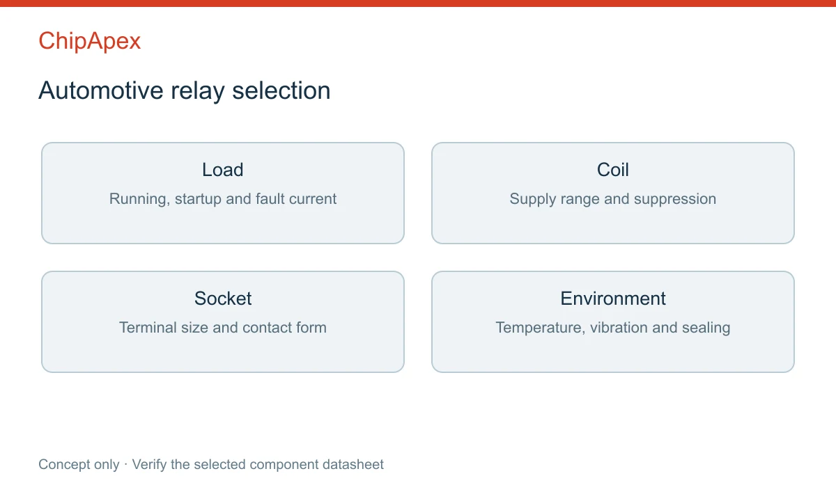
Match the mounting arrangement, terminal size, sealing requirements and temperature range. Vibration, water, dust and chemical exposure can change which construction is appropriate. Sealed and vented designs can also have different processing restrictions.
If a relay clicks but the load does not run, inspect the load supply, fuse, socket, contact voltage drop and downstream wiring. A click confirms movement may have occurred; it does not prove that the contacts carry current correctly. If the load stays on after the coil is de-energized, welded contacts are one possibility, but an alternative feed path or wiring fault must also be considered.
Use the specified test procedure with the circuit in a safe state. A continuity check on an unloaded contact does not replace a voltage-drop or temperature assessment under an appropriate controlled load. Avoid repeated cycling into a known short circuit.
Send ChipApex the manufacturer part number, coil voltage, contact form, load type, operating current, startup conditions and quantity. Include the socket drawing or original schematic when replacing an existing component. The broader relays category is useful when the application needs another relay construction.
Request confirmation against the exact part datasheet and current availability. Similar packaging alone is insufficient evidence of a substitute. Manufacturer automotive relay product documentation also shows why coil, contact and package options must be checked at part-number level.
Only if the contact arrangement, terminal positions, coil characteristics and relevant ratings match the circuit. An additional terminal may introduce a normally closed path or a second normally open output.
A 24 V coil may fail to operate reliably from 12 V. Select the rated coil and verify its pickup and release limits across the vehicle's actual supply range.
The coil dissipates power, and load current produces losses in contacts and connections. Excessive heat may indicate overload, poor crimps, corrosion or an unsuitable operating environment.
No. The relay controls switching; the fuse provides defined overcurrent protection. Their functions and selection criteria are different.
No. Read the relay diagram and socket documentation. Do not infer electrical compatibility from the number of terminals.
Compare RC, crystal and MEMS oscillator circuits. Check ppm, jitter, load capacitance, startup margin and output compatibility before choosing a clock source.
View details
See how a MEMS gyroscope measures angular rate, why its angle estimate drifts, and which range, noise, interface and temperature specs to compare.
View details
What is EEPROM? Learn byte-level storage, EEPROM vs Flash, I2C/SPI, BOM selection & sourcing risks. Authentic EEPROMs at ChipApex.
View details
Understand thermal fuse operation, Tf, Th and Tm, electrical ratings and mounting. Check temperature limits and replacement requirements for your design.
View details
The activity of extra discounts on wholesale prices is in full swing…
Please fill in your contact information and we will send you the latest wholesale price list.

