 ChipApex | Global Electronic Components Supplier

SEARCH
Search Product
Search Post
— IC芯片 | 连接器 | 传感器 | 被动器件 —
Search productSearch post
— IC芯片 | 连接器 | 传感器 | 被动器件 —
The trend of science and technology is changing rapidly.
A reed relay combines a magnetically operated reed switch with a coil. Energizing the coil changes the state of metal contacts sealed inside a small capsule. This arrangement is useful in test equipment and signal routing, where leakage, contact resistance and isolation can matter as much as load current.
The sealed capsule does not make the contacts solid-state or eliminate wear. To choose reed relays, define the signal conditions during switching as well as the conditions while the contact is already closed.
The coil creates a magnetic field around the reed contacts. In a normally open design, the field pulls the contacts together; removing it allows them to separate. Other contact forms are available, so check whether the circuit requires normally open, normally closed or changeover behavior.
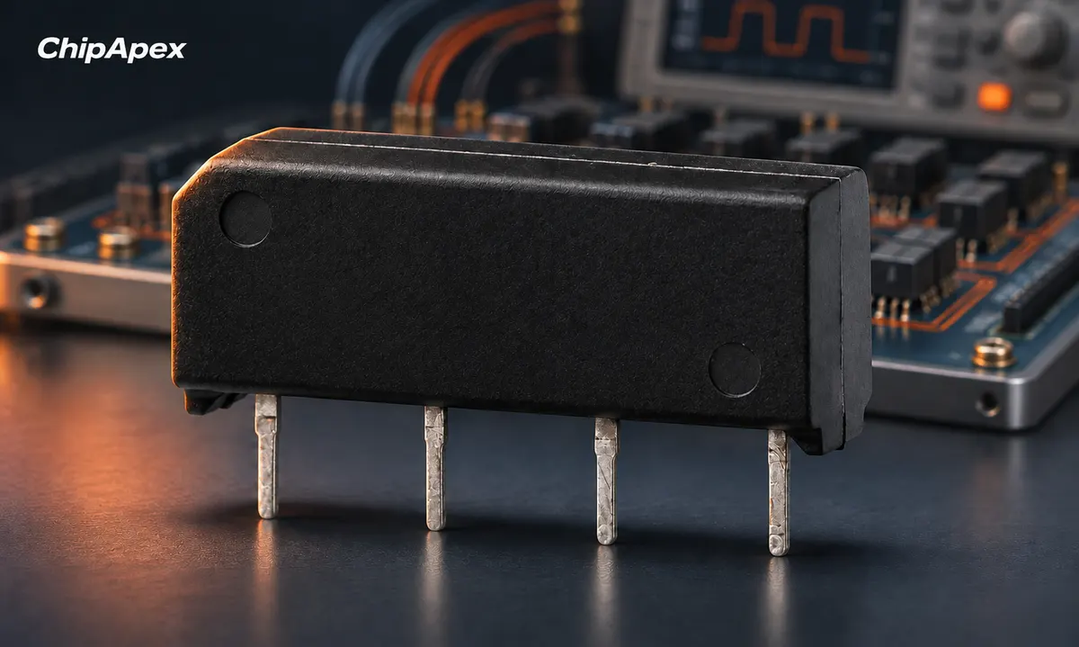
A reed switch and a reed relay are related but different products. A bare reed switch may be actuated by an external magnet. A reed relay includes an electromagnetic actuator and may include shielding or suppression components. The manufacturer's explanation of reed relay construction describes the sealed contact and coil arrangement.
In an instrument, the relay might route a low-level sensor signal, select a resistance range or connect a device under test. Those applications have different requirements from switching a lamp or motor. Start with the signal being measured and the error the switching path can tolerate.
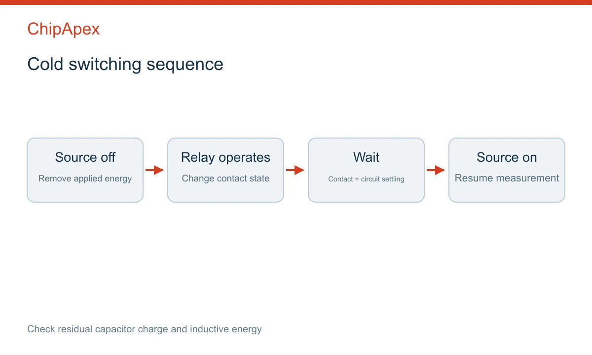
Hot switching means contacts make or break while appreciable voltage or current is present. Cold switching means the source is removed or reduced to an acceptable level before the contact changes state, then restored after the contact has settled.
| Operation | Contact condition | Main concern |
|---|---|---|
| Hot make | Energized circuit closes | Inrush, arcing and contact damage |
| Hot break | Current path opens | Inductive energy and arcing |
| Cold switching | Signal removed before operation | Sequencing and settling time |
| Carrying | Closed contact conducts | Heating and carrying-current limit |
A relay's carrying-current rating is not necessarily its switching-current rating. Similarly, a voltage withstand specification across an open contact does not establish the voltage it can repeatedly switch under load. Treat each limit independently.
Stored energy can defeat an apparently cold-switching sequence. A charged capacitor may discharge into the closing contact even after the main source has been disabled. Check cable capacitance, input capacitors and residual charge. Inductance can cause a transient when the path opens. Specify discharge and settling behavior explicitly.
For a high-impedance measurement, insulation resistance and leakage can dominate the error budget. Board contamination, moisture and connector leakage may matter as much as the relay. Guarding and careful cleaning can be necessary, but they must suit the instrument architecture and manufacturing process.
For a low-resistance measurement, contact resistance and its stability become important. Four-wire measurement can remove some lead and contact resistance from the sensed result when implemented correctly. It does not eliminate all errors or make the current path irrelevant.
Thermal electromotive force is another concern when measuring very small voltages. Temperature gradients and dissimilar metals can produce an unwanted offset. Coil heating, switching sequence and settling time can therefore affect a precision measurement even when the contacts appear electrically stable.
If the downstream circuit uses an instrumentation op amp, evaluate its input bias current and common-mode range together with relay leakage and source impedance. When comparing an adc converter, include the time needed for the whole switched signal path to settle before acquisition.
Isolation specifications need a clear reference: contact-to-contact, contact-to-coil and contact-to-shield are different paths. Working voltage, test voltage and transient withstand also mean different things. Do not substitute a short-duration test result for an allowable continuous operating condition.
Magnetic shielding can reduce interaction between nearby relays. Electrostatic shielding addresses electric-field coupling and is a separate feature. Check the shield connection and PCB arrangement recommended by the manufacturer. A shield is not effective merely because it appears in the part description.
Operate time, release time and bounce define when the contact can change state, but the instrument may require additional settling time. For multiplexed measurements, include amplifier recovery, filter settling and ADC acquisition in the timing budget. The fastest relay is not automatically the fastest complete measurement channel.
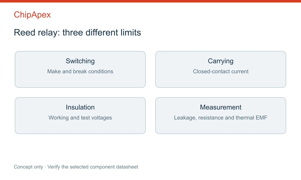
Record the following before choosing a part:
For high-voltage work, include spacing and insulation requirements for the complete PCB and enclosure. A high-voltage-rated relay cannot compensate for inadequate board clearance. In a dense switching matrix, also check coil power and magnetic interaction at the intended number of simultaneously energized channels.
Use the reed relay category to prepare a focused sourcing request. Send ChipApex the preferred part number, operating conditions and quantity, and identify whether an alternative must preserve an existing footprint. Request part-specific documentation before approving a replacement.
No. It uses moving metal contacts operated by a magnetic field. A solid-state relay switches through semiconductor devices and has different leakage, resistance and drive characteristics.
Some models can, but the required switching voltage, open-contact withstand, load energy and insulation conditions must all be within the specific part's ratings.
Making or breaking the circuit may exceed a separate switching limit. Inrush, stored capacitive energy and inductive transients can be missed if only steady current is considered.
No. Mechanical operation still occurs, and residual energy may remain. Correct source sequencing reduces electrical stress but does not remove every failure mechanism.
Check contact settling, coil heating, thermal offsets, leakage, amplifier recovery and ADC acquisition timing. Repeat the measurement after a controlled settling interval to help isolate the cause.
Compare Hall, shunt, current transformer and Rogowski sensing. Check AC/DC capability, accuracy, isolation, heat and response before selecting a sensor.
View details
Choose an ADC converter by resolution, sample rate, noise and input design. Review practical tradeoffs and prepare component requirements for ChipApex.
View details
Learn how a diode conducts, how to identify anode and cathode, and when to choose rectifier, TVS, Zener or photodiode types for a circuit.
View details
Compare RC, crystal and MEMS oscillator circuits. Check ppm, jitter, load capacitance, startup margin and output compatibility before choosing a clock source.
View details
The activity of extra discounts on wholesale prices is in full swing…
Please fill in your contact information and we will send you the latest wholesale price list.

