 ChipApex | Global Electronic Components Supplier

SEARCH
Search Product
Search Post
— IC芯片 | 连接器 | 传感器 | 被动器件 —
Search productSearch post
— IC芯片 | 连接器 | 传感器 | 被动器件 —
The trend of science and technology is changing rapidly.
A push button switch changes an electrical contact state when its actuator is pressed. A momentary button returns when released, while a latching button holds its new state until another action resets it. To choose a replacement, match that action, the contact arrangement, the switched load and the mounting dimensions before comparing appearance.
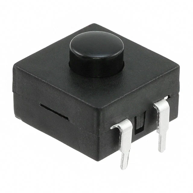
Mechanical action and contact arrangement describe different properties. A momentary normally open contact closes while you hold the button and opens when you release it. A normally closed contact does the opposite. A changeover contact switches a common terminal between two paths. A latching push button retains a state after the actuator is released.
A push-push mechanism typically changes state on successive presses. Confirm the manufacturer’s operating diagram because alternate-action mechanisms and reset methods vary. The feel of a button alone cannot establish its electrical function.
| Selection question | What to specify |
|---|---|
| Should the circuit stay changed after release? | Momentary or alternate-action/latching |
| What happens in the resting state? | Normally open, normally closed or changeover |
| How many independent circuits switch? | Poles and the actual contact diagram |
| Is illumination required? | Lamp supply and terminals, separately from switched contacts |
Panel-mounted controls and miniature PCB switches serve different mechanical layouts. This guide focuses on the action, electrical rating and panel fit of a push button. ChipApex’s pushbutton switches category can help identify the family before you compare the detailed drawing.
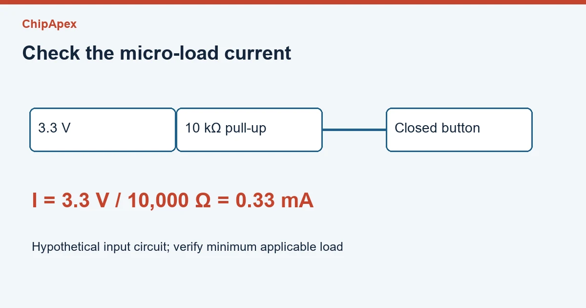
Check the rating at the actual load voltage and current type. AC and DC ratings can differ, and a resistive-load rating does not automatically cover a motor, solenoid or capacitive input. For a coil, review the inrush and the suppression circuit. Suppression can change the release behavior of an actuator, so consider the complete control circuit.
Low current needs attention too. A switch selected for a substantial power load may have a minimum applicable load that a logic input never reaches. Contact materials and the environment affect that behavior. OMRON’s basic switch precautions describe the need to match load characteristics and micro-load use.
Consider a hypothetical 3.3 V MCU input with a 10 kΩ pull-up and a button connecting it to ground. When pressed, the steady current is approximately 3.3 ÷ 10,000 = 0.33 mA. Select a contact system specified for that signal duty. A large ampere marking by itself gives little information about performance at this current.
Mechanical contacts also bounce. Hardware filtering or firmware can require a stable input before recognizing a press. Determine the debounce interval from the switch specification and the actual circuit, including how quickly the control must respond. The tactile switch guide covers related PCB switch considerations.
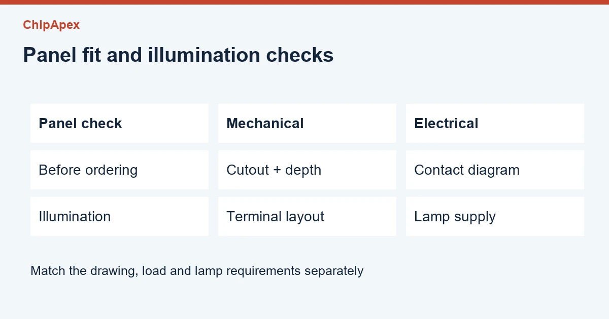
Two buttons can fit the same panel hole and still be incompatible electrically. Before ordering, record panel thickness, cutout size, actuator travel and the clearance behind the panel. Include the contact block and retaining hardware in the depth check. For a sealed control, verify whether its environmental rating applies to the front face, the complete assembly or a particular installation.
Illuminated push button switches can have contacts that are isolated from the lamp circuit. A four-terminal device might have two lamp connections and two switch connections, but layouts differ. Use the terminal drawing. Lamp voltage, polarity and any built-in current limiting need their own check.
A useful RFQ describes a specific control. For example, “momentary, one normally open contact, suitable for a 3.3 V logic input, panel thickness 2 mm, illuminated from a separately specified supply.” Add the manufacturer part number and drawing when available. ChipApex lists related switches, but the drawing and load requirements determine the replacement.
A momentary contact returns to its normal state when actuation ends. A latching or alternate-action control retains its state. Decide which behavior the equipment expects before selecting a part. A control circuit can also store a command electronically even when the physical button is momentary, so check both the button and the circuit.
Only if its documented rating covers the actual motor duty, voltage, current and operating conditions. Many control buttons instead energize a contactor or send a signal to a controller. Check the equipment’s switching arrangement and approved replacement specification rather than extrapolating from a general current rating.
NO and NC describe the normal contact state relative to actuation as defined by the manufacturer. “On” and “off” describe what the equipment does. A normally closed stop button can keep a control path energized during normal operation. Read the contact diagram with the circuit drawing.
Contact bounce can create several transitions during one mechanical action. An unstable pull-up, electrical noise or software handling can produce similar symptoms. Inspect the input waveform and confirm that the receiving circuit recognizes a deliberate press with an appropriate stable-state requirement.
That depends on the lamp assembly. A bare LED needs suitable current control, while some illuminated controls include components for a stated supply. Use the lamp specification and terminal diagram. Avoid assuming that the switched-load voltage is also the correct illumination supply.
For a ChipApex quote, include the required action, contact arrangement, load, panel drawing, illumination supply and quantity.
Choose a DIP switch by contact type, coded positions, footprint and signal ratings. Check logic polarity, assembly conditions and PCB configuration behavior.
View details
Learn how optical sensing works, compare detection methods, and select sensors by target surface, ambient light, response time and electrical interface.
View details
Learn what a transistor does in a circuit. Compare switching and amplification, BJT and MOSFET drive, operating limits and practical component selection.
View details
Learn how a thermostat in a heater works. Check hysteresis, reset mode, thermal placement and contact ratings before selecting a mechanical control.
View details
The activity of extra discounts on wholesale prices is in full swing…
Please fill in your contact information and we will send you the latest wholesale price list.