 ChipApex | Global Electronic Components Supplier

SEARCH
Search Product
Search Post
— IC芯片 | 连接器 | 传感器 | 被动器件 —
Search productSearch post
— IC芯片 | 连接器 | 传感器 | 被动器件 —
The trend of science and technology is changing rapidly.
A thermostat in a heater regulates temperature by changing the state of a control or power circuit. A mechanical thermostat responds to temperature through a physical sensing element, often a bimetal mechanism. Its operating temperature, reset behavior, thermal contact and electrical ratings determine how it performs in the heater.
The temperature marked on a component describes a specified sensing and switching condition. The air, heating element and enclosure can each be at a different temperature. A useful selection process starts by identifying what the thermostat is intended to sense and control.
A bimetal element combines materials that expand differently as temperature changes. The resulting movement operates a contact mechanism. A snap-action construction changes contact state rapidly around its operating point, while other constructions may use a different mechanical arrangement.
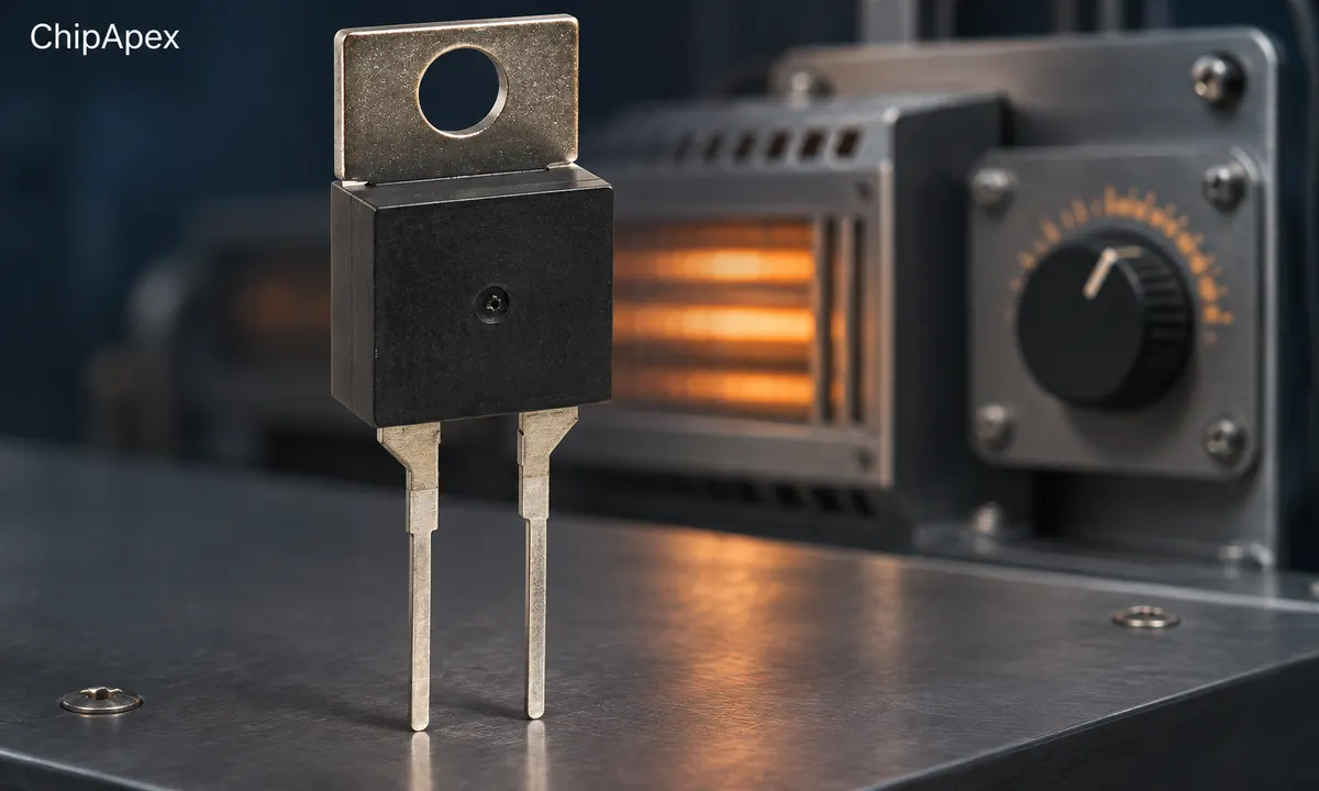
For an open-on-temperature-rise heating control, the contact opens as the sensed temperature reaches the specified operating condition. It closes again after cooling to the reset condition if it is an automatic-reset design. Close-on-rise versions are also available for other functions, so verify the contact operation explicitly.
Thermostats may sense a surface, surrounding air or a remote location through a suitable sensing arrangement. Mounting a surface-sensing part loosely in moving air can produce a different response from the intended installation. The manufacturer's bimetal thermostat datasheet illustrates how contact operation, mounting and temperature conditions are specified separately.
Hysteresis, also called the switching differential in this context, separates the operating and reset temperatures. It creates a temperature interval over which the contact retains its previous state. This reduces repeated switching around a single threshold.
For a hypothetical open-on-rise thermostat that opens at 80°C and recloses at 70°C, the nominal differential is 10°C. This example describes the component's switching points. The heater's controlled temperature can vary further because of thermal lag, placement and stored heat.
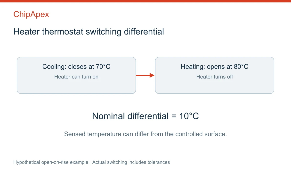
A narrow differential may provide tighter switching control but increase cycle frequency in a particular thermal system. A wider differential may reduce cycling while allowing a larger temperature change. Assess the application's thermal behavior and the thermostat's permitted electrical life together.
Operating-point tolerance and differential tolerance also affect the result. A nominal label does not establish the exact temperature of every produced unit. Manufacturer thermostat temperature-ordering guidance shows the importance of specifying both upper and reset conditions.
| Construction | Behavior after cooling | Typical design question |
|---|---|---|
| Automatic-reset thermostat | Returns according to its reset characteristic | Is repeated cycling appropriate? |
| Manual-reset thermostat | Requires the specified reset action | Should an abnormal event require inspection? |
| Adjustable thermostat | Allows a setting change within its design range | How do adjustment and tolerances affect control? |
| Electronic temperature control | Uses a sensor and control electronics | What accuracy, logic and diagnostics are required? |
A thermostat can provide normal temperature regulation or serve a limiting function when designed and rated for that purpose. The role must be clear in the heater's architecture. Resetting an overtemperature event without understanding its cause can simply repeat the fault.
A thermal fuse has a different recovery behavior and is often part of an independent overtemperature protection arrangement. Coordinate control and protection using the appliance design requirements. Their temperature labels and mounting locations cannot be compared in isolation.
Check voltage, current, load type and required number of cycles. A resistive-load rating does not automatically apply to a motor, transformer or electronically controlled load. AC and DC interruption conditions can also require different ratings.
For an illustrative 1,500 W resistive heater operating at 230 V, nominal current is about 6.5 A from I = P/V. Supply tolerance, element behavior, operating temperature and the selected contact rating still need assessment. This calculation cannot establish an acceptable thermostat model by itself.
If the thermostat operates a separate switching stage, the contact sees that stage's input or coil characteristics. Appropriate relays can separate a small control function from a larger load, subject to the complete circuit design. Coil suppression and contact behavior should be evaluated together.
Terminal resistance also matters. A loose or unsuitable connection can generate heat near the sensing element, alter operation and damage the assembly. Follow the part's connection and mounting requirements, including any restrictions on soldering or mechanical stress.
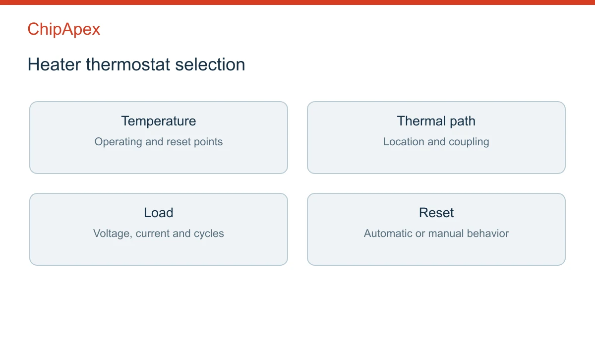
Thermal coupling determines how quickly the sensing element follows the controlled part. Contact pressure, mounting surface, insulation, airflow and the distance from the heat source can change the response. Use the specified mounting arrangement and validate it in the actual assembly.
Stored heat can continue raising the load temperature after the contact opens. This overshoot depends on the heater's thermal mass and heat transfer. Changing the thermostat location or set point may alter it, but the final design needs a complete operating-cycle test.
In systems with electronic control, temperature sensors may monitor a different location or provide a continuous reading. Compare the sensing locations before interpreting a disagreement between a displayed value and a thermostat's switching event.
Frequent cycling can result from a narrow differential, poor airflow, unsuitable placement or excessive heating near the thermostat. Slow response can arise from weak thermal contact or a sensing location that follows the controlled temperature too late.
If the heater remains cold, possible causes include an open contact, an unreset limiting device, wiring faults or a separate protection component. If it continues heating beyond the intended condition, investigate the control path, contact state and thermal coupling. Use qualified service procedures appropriate to the equipment and a de-energized inspection where required.
Replacement selection should preserve the intended function. Check the operating and reset temperatures, open-on-rise or close-on-rise behavior, tolerance, reset mode, load rating, terminals and mounting. Similar package outlines can conceal different switching functions.
Review ChipApex's thermostat in heater category with the original part number, required temperature conditions and mechanical drawing. Include the electrical load, reset behavior, expected cycling and quantity. These details help identify which candidates need a closer datasheet comparison.
The thermostat may be sensing a local surface or warm airflow rather than the room temperature. Another limiting device may also be operating. Compare the intended sensing location, airflow and control sequence before interpreting the event as a failed thermostat.
Only when the specified sensing arrangement and thermal conditions establish that relationship. Temperature gradients and response delays can separate the thermostat element from the heater surface. Validate the actual sensing location during warm-up, steady cycling and cooling.
The replacement must preserve the equipment's temperature limits and protection design. Raising the operating temperature can expose insulation, surrounding components or the load to additional heat. Use the approved specification and investigate why the original control is operating.
It means the specified contact opens as the sensed temperature rises through its operating condition. An automatic-reset version later closes according to its reset characteristic. The part documentation defines tolerances, contact state and temperature conditions for that behavior.
They may differ in reset temperature, tolerance, thermal mass, sensing construction or mounting. Their contact ratings and reset modes may differ as well. Compare the complete part specification and installed response rather than relying on one printed temperature.

Choose a reed relay for signal switching. Understand hot and cold switching, leakage, contact resistance, isolation and measurement settling requirements.
View details
Learn how to use ferrite beads for noise filtering. Check impedance, DC bias, placement, resonance and load-step behavior before selecting a part.
View details
Discover why SRAM remains essential in industrial, medical & aerospace systems—thanks to its deterministic performance and long-term reliability. Trusted by engineers worldwide.
View details
Understand UART protocol framing, baud rate and electrical interfaces. Learn 8N1 timing, TX/RX wiring, buffering and practical troubleshooting steps.
View details
The activity of extra discounts on wholesale prices is in full swing…
Please fill in your contact information and we will send you the latest wholesale price list.

