 ChipApex | Global Electronic Components Supplier

SEARCH
Search Product
Search Post
— IC芯片 | 连接器 | 传感器 | 被动器件 —
Search productSearch post
— IC芯片 | 连接器 | 传感器 | 被动器件 —
The trend of science and technology is changing rapidly.
A variable capacitor provides a capacitance that can be deliberately adjusted. Mechanical versions change the geometry of their electrodes, while electronic tuning devices change capacitance through an applied control condition. These components adjust resonance, matching and other circuit behavior where a fixed capacitance would provide insufficient control.
The term covers several constructions. An air-variable tuning capacitor, a small trimmer and a reverse-biased varactor diode require different mechanical, voltage and RF checks. Identify the tuning method before comparing nominal capacitance values.
Capacitance depends on the electrode arrangement and the material between them. Mechanical designs vary factors such as plate overlap or spacing. A trimmer provides an adjustment usually made during calibration, while a panel-operated variable capacitor may support repeated user adjustment.
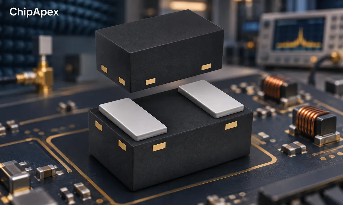
Electronic tuning uses a component whose capacitance changes with bias. In a varactor diode, the reverse-biased junction provides a voltage-dependent capacitance. ChipApex's variable capacitor category contains varicap and varactor components, so the exact device construction should guide selection.
Some electronically tunable capacitors use other materials or switching architectures. The control method, signal handling and tuning curve depend on the technology. A shared capacitance range alone does not establish equivalent behavior.
| Type | Adjustment method | Checks before selection |
|---|---|---|
| Mechanical tuning capacitor | Changes electrode geometry | Capacitance range, voltage, current and mechanical travel |
| Trimmer capacitor | Small mechanical adjustment | Adjustment range, setting stability and assembly access |
| Varactor diode | Changes reverse bias | C-V curve, Q, signal level and bias limits |
| Other electronic tuning device | Technology-specific control | Control range, RF performance and interface requirements |
Mechanical tuning can suit an accessible manual adjustment. Electronic tuning can be controlled by a voltage source and incorporated into a feedback system. The preferred method depends on adjustment speed, power handling, size and the way the equipment is operated.
The variable-capacitor overview provides an example of electronic tuning technology. It should be read alongside the selected component's datasheet because different families use different mechanisms and operating conditions.
In a conventional reverse-biased varactor, increasing reverse voltage generally reduces junction capacitance over its specified operating region. The amount of change and the shape of the curve depend on the junction design. Compare capacitance at the actual bias points available in the circuit.
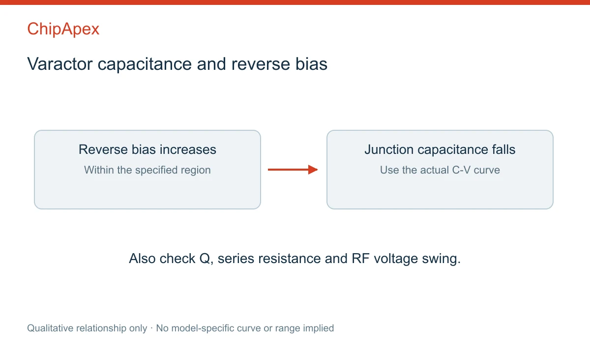
A tuning ratio must identify its measurement voltages and conditions. A large ratio measured over a wide voltage range may be unusable with a low-voltage control supply. Include the minimum bias, maximum bias, control-source swing and component tolerances in the range calculation.
RF voltage is superimposed on the DC bias. The instantaneous terminal voltage must remain within the selected device's suitable operating region. Large signal swings can produce distortion, forward conduction or excessive stress even when the average bias looks acceptable.
The manufacturer's varactor application note describes junction capacitance, series resistance and package parasitics. These quantities need to be evaluated together when the part operates in an RF circuit.
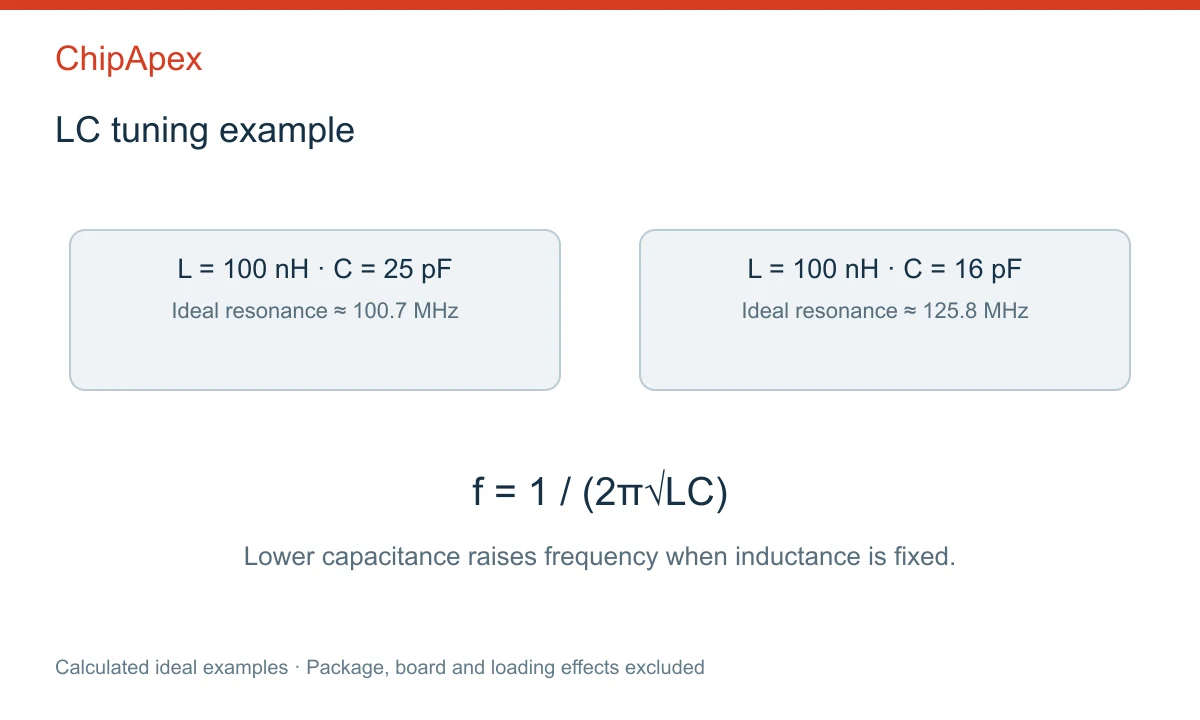
For an ideal LC resonator, the resonant frequency is f = 1/(2π√LC). If inductance remains constant, reducing capacitance raises the resonant frequency. Real circuits include fixed and parasitic capacitances, so the tuning range may be smaller than a calculation using the variable element alone suggests.
As an idealized example, 100 nH with 25 pF resonates at approximately 100.7 MHz. Reducing capacitance to 16 pF raises the calculated frequency to about 125.8 MHz. These values exclude package, board and loading effects and provide no part-specific performance guarantee.
When choosing inductors, include tolerance, loss and self-resonant behavior. The complete network's parasitics can dominate once the intended capacitance is small. Measure the assembled circuit and compare its response with a model that includes realistic component behavior.
Q relates reactive behavior to loss under stated conditions. In a simplified capacitive model, Q is approximately 1/(2πfCRs), where Rs is the relevant series resistance. Because capacitance and resistance can change with bias, a Q value at one test point cannot describe every tuning condition.
Loss can reduce resonator selectivity or change the behavior of an oscillator and matching network. Check the selected device at the intended frequency and bias. A capacitance match with poor loss performance may fail to meet the system requirement.
Package inductance and capacitance also influence the response. Single and dual-junction packages have different connections and equivalent circuits. Confirm pin functions, common-node arrangements and the manufacturer's model before replacing one device with another.
For an rf signal with substantial amplitude, review RF current, voltage swing, distortion and heating. A component suitable for low-level tuning may be unsuitable for a high-power matching network. Working conditions should come from the exact device documentation.
The bias network must supply the intended control voltage while limiting unwanted RF loading and coupling. Its components can add noise, loss and an additional frequency response. Choose the arrangement using the RF design and manufacturer guidance.
Noise on the bias line can change capacitance and modulate a tuned circuit. Leakage, control-source impedance and temperature can affect stability. Measure tuning behavior with the actual control source connected, including its startup and shutdown states.
Check endpoints across component tolerance, supply variation and temperature. If the adjustment cannot reach the required frequency on some units, investigate fixed capacitance, parasitics and available control swing. Selecting a wider nominal tuning ratio may leave other constraints unresolved.
Send ChipApex the preferred part number, required capacitance at stated bias points, frequency range, loss or Q target, expected signal level, package and quantity. For a mechanical part, add adjustment access, voltage and mechanical requirements. This makes the intended tuning method clear before alternatives are evaluated.
A varactor is one electronic way to obtain variable capacitance. The broader category also includes mechanical tuning capacitors, trimmers and other electronic technologies. Identify the required adjustment method and operating conditions before comparing candidates by capacitance range.
In an ideal LC resonator with fixed inductance, increasing capacitance lowers resonant frequency. The actual circuit also contains fixed and parasitic elements, so the measured tuning relationship should be checked against the complete network model and assembled hardware.
That change usually requires a bias source and circuit redesign. Voltage swing, loss, tuning range, linearity and power handling can differ substantially. Compare the complete operating conditions and control architecture before treating the two constructions as substitutes.
Fixed and stray capacitance may represent a significant portion of the total. The available bias range, device tolerance and loading can also restrict tuning. Compare capacitance at the actual operating points and include package and board parasitics in the calculation.
Check capacitance at specified voltages, tuning curve, Q or series resistance, leakage, voltage limits, package and junction arrangement. Also evaluate signal amplitude and temperature behavior. A single capacitance number does not establish equivalent tuning performance.
Learn how a diode conducts, how to identify anode and cathode, and when to choose rectifier, TVS, Zener or photodiode types for a circuit.
View details
Plan electronics thermal management with power-loss estimates, thermal metrics, sensor placement and fan control. Check heat paths and validate your system.
View details
Choose a vibration sensor for machine monitoring. Compare sensing methods, bandwidth, noise and mounting, then define the signal-chain requirements.
View details
Learn how NAND flash works, its types (SLC, MLC, TLC), applications in SSDs & embedded systems, and how to source authentic, traceable ICs from trusted suppliers.
View details
The activity of extra discounts on wholesale prices is in full swing…
Please fill in your contact information and we will send you the latest wholesale price list.

