 ChipApex | Global Electronic Components Supplier

SEARCH
Search Product
Search Post
— IC芯片 | 连接器 | 传感器 | 被动器件 —
Search productSearch post
— IC芯片 | 连接器 | 传感器 | 被动器件 —
The trend of science and technology is changing rapidly.
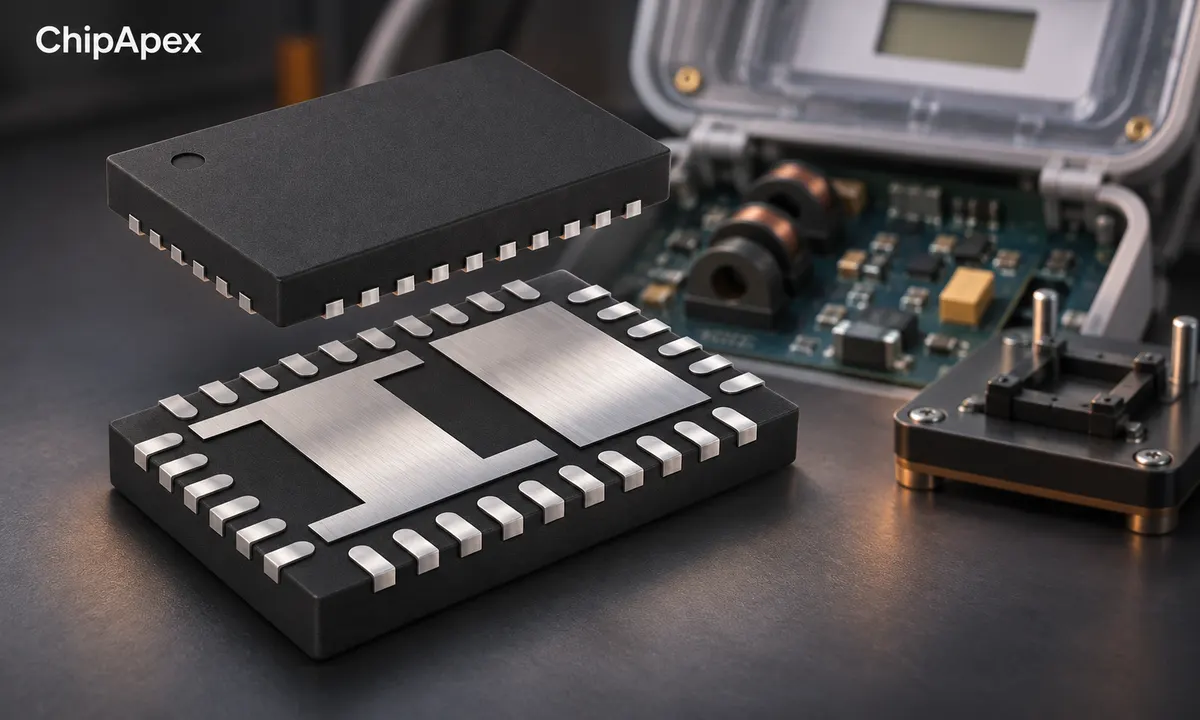
An electric energy meter measures electrical energy transferred over time, commonly displaying the result in kilowatt-hours. An electronic meter samples voltage and current, calculates power and accumulates energy. Its sensors, analog inputs, timing, calibration and software together determine the accuracy of the complete instrument.
A finished utility meter also contains communication, display, insulation and other functions appropriate to its application. For equipment designers, understanding the measurement chain helps identify the sensing components and energy metering IC functions required on the board.
Power is the rate of energy transfer. Energy is the accumulated amount over an interval. A load using a steady 1 kW for 2 hours consumes 2 kWh. If its power changes, the meter must account for the changing value throughout the interval.
A displayed voltage or current alone cannot establish energy use. The meter needs a suitable relationship between both waveforms and time. For AC loads, current may be phase-shifted or distorted, making a simple multiplication of RMS voltage and RMS current insufficient to determine active power.
An energy register may represent imported energy, exported energy or another defined measurement. Check the meter's register labels and scaling. For a straightforward cumulative consumption register, energy used over an interval is the later reading minus the earlier reading, subject to the instrument's documented behavior.
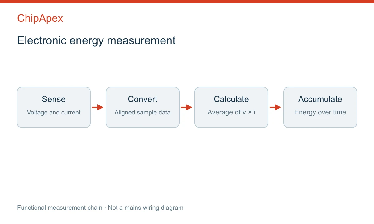
The measurement chain starts with suitable voltage and current sensing. The resulting signals are conditioned and sampled. Digital processing calculates the required electrical quantities, and an accumulator integrates energy over time.
The voltage path may use an appropriately designed divider or another sensing arrangement. Current measurement may use a shunt, current transformer or magnetic sensor. Their suitability depends on AC or DC operation, isolation requirements, current range and the complete system architecture.
Compare current sensors by the waveform and range they must measure. In a transformer-based path, frequency response and phase error can matter as much as amplitude error. In a shunt path, resistance, heat and the input circuit's common-mode conditions need attention.
An analog front end can provide gain, filtering and conversion functions. A more integrated metering IC may also calculate RMS values, power and energy. Manufacturer power-monitoring documentation illustrates how these functions can be combined in one device.
Active power is the time average of instantaneous voltage multiplied by instantaneous current over the relevant interval. For a sinusoidal single-phase case, P = Vrms × Irms × cosφ, where φ is the phase difference between voltage and current.
Apparent power is S = Vrms × Irms. True power factor is P/S when those quantities are defined consistently. With distorted waveforms, true power factor includes effects beyond the phase displacement of the fundamental components.
| Quantity | Common unit | Meaning in the measurement |
|---|---|---|
| Active power | W or kW | Average rate of net energy transfer |
| Apparent power | VA or kVA | Product of RMS voltage and current |
| Reactive power | var or kvar | Reactive component under the defined calculation method |
| Active energy | Wh or kWh | Active power integrated over time |
For sinusoidal voltage and current, reactive power can be expressed as Q = Vrms × Irms × sinφ. Under distortion, reactive-power definitions and implementation methods require closer attention. Compare the required measurement method with the metering IC's documentation.
As an illustrative sinusoidal example, 230 V RMS and 5 A RMS give 1,150 VA. At a power factor of 0.8, active power is 920 W. If that active power remains steady for 2 hours, active energy is 1.84 kWh. These values describe a calculation example and do not establish a particular meter's accuracy.
Voltage and current must be sampled or aligned sufficiently well for the intended measurement. Timing differences between channels can appear as phase error. Sensor phase shift and input filters can contribute additional mismatch.
In a sinusoidal case, the sensitivity to a small phase error increases as the displacement power factor falls. A calibration that looks satisfactory with a nearly resistive load can therefore miss a larger error at another operating point. Test representative current levels, power factors and waveforms.
When selecting a separate adc converter, compare channel timing, input range, noise and conversion behavior. Resolution alone cannot establish the system's ability to measure a small current accurately while tolerating a large peak.
Anti-alias filtering must suit the sampling scheme and the relevant waveform bandwidth. Filtering the two paths differently can change their relative phase. The permitted network and any compensation method should follow the converter and metering algorithm requirements.
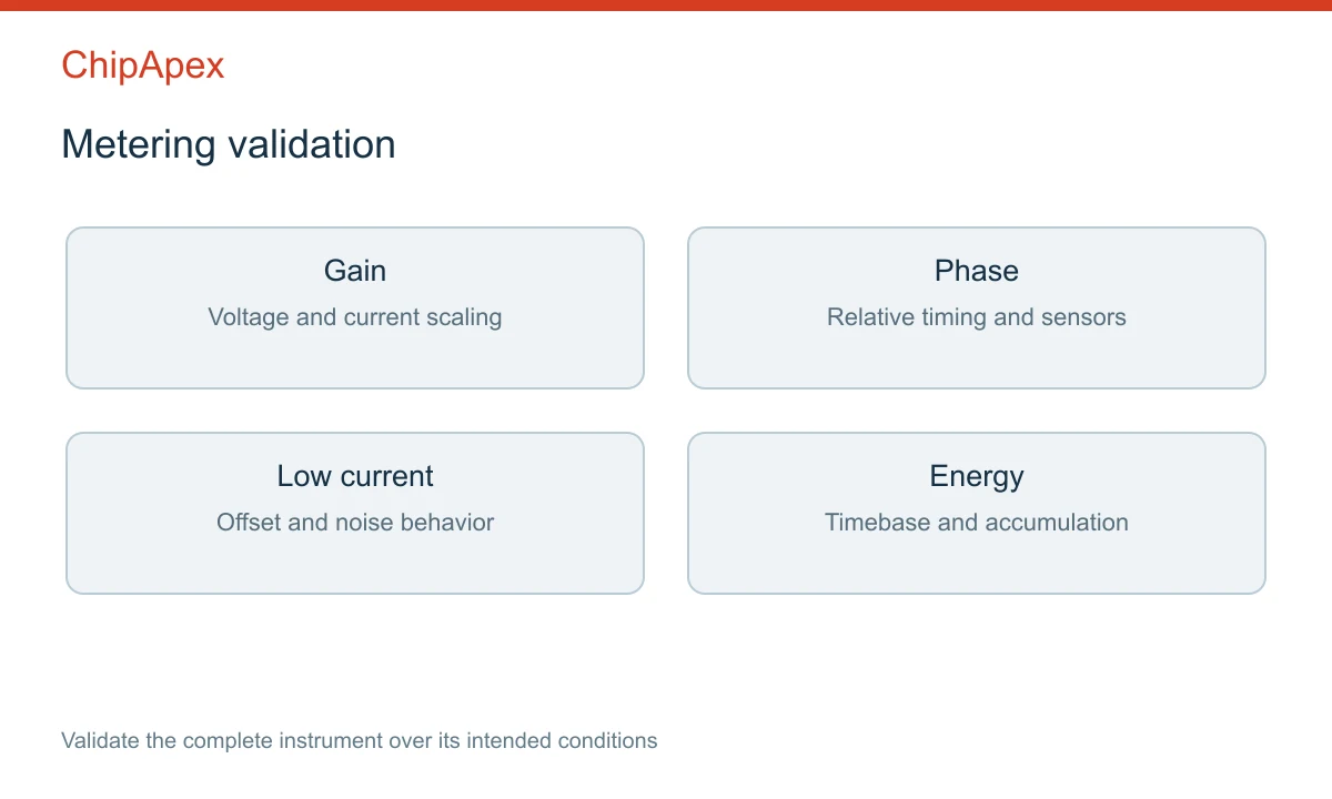
Gain calibration adjusts scale errors in the voltage or current path. Offset correction addresses applicable zero or low-signal errors. Phase compensation can reduce specified differences between sensing paths. These corrections address different mechanisms and should be evaluated separately.
Use an appropriate reference source or reference instrument with understood uncertainty. Record voltage, current, frequency, waveform, temperature and the averaging interval. A single calibration point cannot establish performance across every condition.
Manufacturer phase-compensation documentation demonstrates why the calibration load and expected phase relationship must be defined. Follow the procedure for the exact IC and firmware implementation being used.
Also test energy accumulation over a known interval. Check timebase accuracy, scaling, counter width, overflow handling and behavior after power loss. Small errors in a continuously accumulated result can become significant over long operation.
Start with the measurement topology, channel count and single-phase, multiphase or DC requirements. Then specify dynamic range, expected waveform, accuracy target, reporting rate, power supply, interface and package.
Some devices provide converted samples for a host processor. Others provide processed registers for quantities such as RMS current, active power or accumulated energy. Check which functions are implemented in hardware or firmware and which remain the responsibility of the host.
Where an external voltage reference is used, include its noise, drift and loading in the error budget. Where the reference is integrated, use the device's specified behavior rather than assuming that integration removes reference-related error.
Isolation, spacing, protection and the user-accessible interface belong to the complete instrument design. A metering IC specification does not establish that the assembled product satisfies a particular billing or safety requirement. Define any required approvals and testing for the intended market and use.
Send ChipApex the preferred part number, phase configuration, voltage and current sensing arrangement, measurement range, target accuracy, interface, package and quantity. Identify whether the design needs raw samples, calculated power values or energy registers.
For an alternative part, compare register scaling, communications, calibration support and startup behavior alongside the electrical specifications. A change in the measurement architecture can affect the PCB and firmware as well as the component list.
A power measurement reports a rate of energy transfer, commonly in watts. An energy measurement accumulates that rate over time, commonly in watt-hours or kilowatt-hours. One instrument may provide both. Check the displayed quantity, measurement interval and register scaling before interpreting a reading.
Current alone is generally insufficient for an AC load. Voltage, the voltage-current relationship and the time interval are also needed. A simplified estimate may be reasonable under explicitly known conditions, but it should not be treated as a substitute for the required energy measurement.
No. Sensor errors, channel timing, reference drift, noise, input range, calibration and processing all contribute. Higher resolution may help a particular design, but the complete error budget and validation results determine whether the instrument meets its measurement target.
Offsets, noise and sensor behavior become larger relative to a small useful signal. The input gain, dynamic range and low-load processing can also affect the result. Evaluate the complete chain at the minimum current of interest and across the expected temperature range.
That depends on the IC's inputs and calculations as well as the sensing architecture. Some current transformers cannot measure steady DC, and some processing functions assume an AC line. Verify supported operation and calibration requirements for the exact part and application.
Learn what an audio power amplifier is, the differences between Class D and AB, and how to choose the right IC. Includes PCB layout tips and part recommendations. Shop at ChipApex.
View details
Choose logic inverter ICs by thresholds, supply, output drive and delay. Compare standard and Schmitt-trigger inputs, power sequencing and replacement checks.
View details
Learn how an analog front end conditions sensor signals. Compare gain, noise, filtering, ADC settling and integration options before selecting components.
View details
Learn how a JFET works and how to compare bias, leakage, noise and pinout. Review practical selection questions for high-impedance analog circuits.
View details
The activity of extra discounts on wholesale prices is in full swing…
Please fill in your contact information and we will send you the latest wholesale price list.

