 ChipApex | Global Electronic Components Supplier

SEARCH
Search Product
Search Post
— IC芯片 | 连接器 | 传感器 | 被动器件 —
Search productSearch post
— IC芯片 | 连接器 | 传感器 | 被动器件 —
Consult the customer manager about the wholesale price.
consultation hotline:86-132-6715-2157
email:[email protected]
Contact the product manager for consultation. One-stop consultation is available.
Do you want a lower wholesale price? Please send us your inquiry and we will reply immediately.
DURF1060CT is listed in the Diode Arrays range at ChipApex. The manufacturer field lists Littelfuse Inc.. Its product description is DIODE ARRAY GP 600V 5A ITO220AB. Review the specifications below when checking this part for your BOM.
The Littelfuse DURF1060CT is an ultrafast recovery rectifier featuring a common cathode configuration within an electrically isolated ITO-220AB package. It provides a peak inverse voltage of 600V and supports a total average forward current of 10A, with 5A per leg. The device exhibits a maximum reverse recovery time of 50ns and low forward voltage drop characteristics. Thermal resistance from junction to case is rated at 5.0°C/W under DC operation.
Verify the specific ordering suffix against the manufacturer's official documentation to confirm packaging options and lead times. Ensure that the requested variant matches the required thermal and electrical specifications for the intended application environment. Cross-reference the part marking system to validate authenticity and production date codes upon receipt.
Select this component for high-frequency power switching applications requiring low reverse recovery time and high surge current capability. The electrically isolated package facilitates mounting on heatsinks without additional insulators. Consider the thermal resistance rating when designing heat dissipation strategies for continuous operation at elevated temperatures.
This device belongs to the Littelfuse DUR series of ultrafast recovery rectifiers. These components are engineered to meet commercial application requirements by combining low Trr, high-temperature stability, and low leakage. The series is suitable for demanding power conversion environments where fast switching speeds are critical.
Public confirmed substitute part numbers: None identified in verified source material.
The maximum reverse recovery time (trr) is 50 ns, measured at IF=500mA, IR=1A, and Irm=250mA.
The device supports a total average forward current of 10A, with a limit of 5A per leg under a 50% duty cycle at TC =100 °C.
The typical thermal resistance (RθJC) is 5.0 °C/W under DC operation conditions.
Explore related parts through Rectifiers, Diodes, Discrete Semiconductor Products, all product categories.
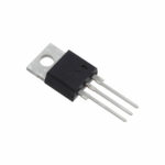 DURF1060CT
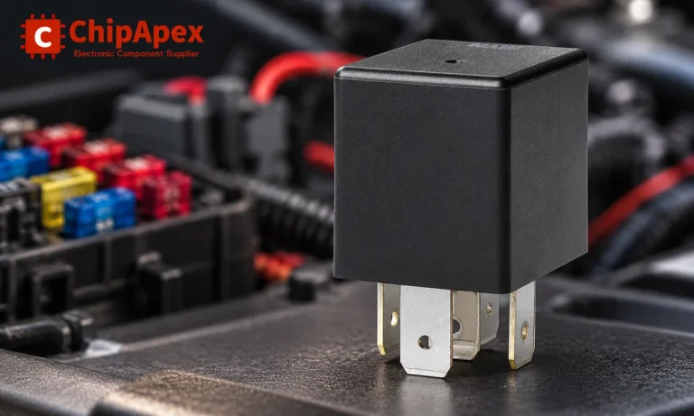
Learn the relay definition, coil and contact operation, NO and NC forms, load ratings and suppression choices. Compare mechanical, reed and solid-state types.
Read More
DURF1060CT is listed in the Diode Arrays range at ChipApex. The manufacturer field lists Littelfuse Inc.. Its product description is DIODE ARRAY GP 600V…
Read More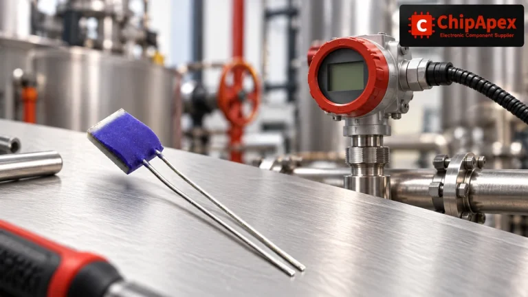
Compare Pt100 and Pt1000 RTDs, two-, three- and four-wire connections, excitation and self-heating. Build an error budget from element to reported temperature.
Read More
DURF1060CT is listed in the Diode Arrays range at ChipApex. The manufacturer field lists Littelfuse Inc.. Its product description is DIODE ARRAY GP 600V…
Read More
DURF1060CT is listed in the Diode Arrays range at ChipApex. The manufacturer field lists Littelfuse Inc.. Its product description is DIODE ARRAY GP 600V…
Read More
DURF1060CT is listed in the Diode Arrays range at ChipApex. The manufacturer field lists Littelfuse Inc.. Its product description is DIODE ARRAY GP 600V…
Read More
DURF1060CT is listed in the Diode Arrays range at ChipApex. The manufacturer field lists Littelfuse Inc.. Its product description is DIODE ARRAY GP 600V…
Read More
DURF1060CT is listed in the Diode Arrays range at ChipApex. The manufacturer field lists Littelfuse Inc.. Its product description is DIODE ARRAY GP 600V…
Read More
DURF1060CT is listed in the Diode Arrays range at ChipApex. The manufacturer field lists Littelfuse Inc.. Its product description is DIODE ARRAY GP 600V…
Read More
DURF1060CT is listed in the Diode Arrays range at ChipApex. The manufacturer field lists Littelfuse Inc.. Its product description is DIODE ARRAY GP 600V…
Read More
DURF1060CT is listed in the Diode Arrays range at ChipApex. The manufacturer field lists Littelfuse Inc.. Its product description is DIODE ARRAY GP 600V…
Read More
DURF1060CT is listed in the Diode Arrays range at ChipApex. The manufacturer field lists Littelfuse Inc.. Its product description is DIODE ARRAY GP 600V…
Read More
The activity of extra discounts on wholesale prices is in full swing…
Please fill in your contact information and we will send you the latest wholesale price list.





