 ChipApex | Global Electronic Components Supplier

SEARCH
Search Product
Search Post
— IC芯片 | 连接器 | 传感器 | 被动器件 —
Search productSearch post
— IC芯片 | 连接器 | 传感器 | 被动器件 —
Consult the customer manager about the wholesale price.
consultation hotline:86-132-6715-2157
email:[email protected]
Contact the product manager for consultation. One-stop consultation is available.
Do you want a lower wholesale price? Please send us your inquiry and we will reply immediately.
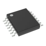
SN74LV126APWRG4 is listed in the Buffers, Drivers, Receivers, Transceivers range at ChipApex. The manufacturer field lists Texas Instruments. Its product description is IC BUF NON-INVERT 5.5V 14TSSOP. Review the specifications below when checking this part for your BOM.
The SN74LV126APWRG4 is a quadruple bus buffer gate with 3-state outputs manufactured by Texas Instruments. It operates within a supply voltage range of 2V to 5.5V and supports mixed-mode voltage operation on all ports. The device features independent line drivers where each output is disabled when the associated output-enable (OE) input is low. It provides a maximum propagation delay of 6.5ns at 5V and includes Ioff support for live insertion, partial power down mode, and back drive protection. Latch-up performance exceeds 250mA per JESD 17.
Verify the specific ordering suffix G4 indicates RoHS compliance and green manufacturing status as defined in the Package Option Addendum. Confirm the package type PW corresponds to TSSOP-14. Ensure the component status is Active rather than NRND or Obsolete before finalizing procurement plans.
Select this component for bus interface applications requiring output ringing minimization due to its low-drive CMOS characteristics. Verify that input voltages do not exceed 5.5V tolerance limits relative to VCC. Ensure unused inputs are tied to high or low bias to prevent undefined operational states during system operation.
This part belongs to the SN74LV126A family of quadruple bus buffer gates. It shares functional similarities with other LV series buffers but is distinguished by its specific 3-state output configuration and 2V to 5.5V operating range. The G4 suffix denotes environmental compliance within the broader product line.
SN74LV126APW
The Ioff feature supports partial power down mode and back drive protection, allowing safe operation when the device is powered off while connected to active buses.
To ensure the high-impedance state during power up or power down, the OE pin should be tied to GND through a pulldown resistor, with the minimum value determined by the driver's current-sourcing capability.
Explore related parts through Logic, Integrated Circuits (ICs), all product categories, ChipApex homepage.
 SN74LV126APWRG4

SN74LV126APWRG4 is listed in the Buffers, Drivers, Receivers, Transceivers range at ChipApex. The manufacturer field lists Texas Instruments. Its product description is IC BUF…
Read More
SN74LV126APWRG4 is listed in the Buffers, Drivers, Receivers, Transceivers range at ChipApex. The manufacturer field lists Texas Instruments. Its product description is IC BUF…
Read More
SN74LV126APWRG4 is listed in the Buffers, Drivers, Receivers, Transceivers range at ChipApex. The manufacturer field lists Texas Instruments. Its product description is IC BUF…
Read More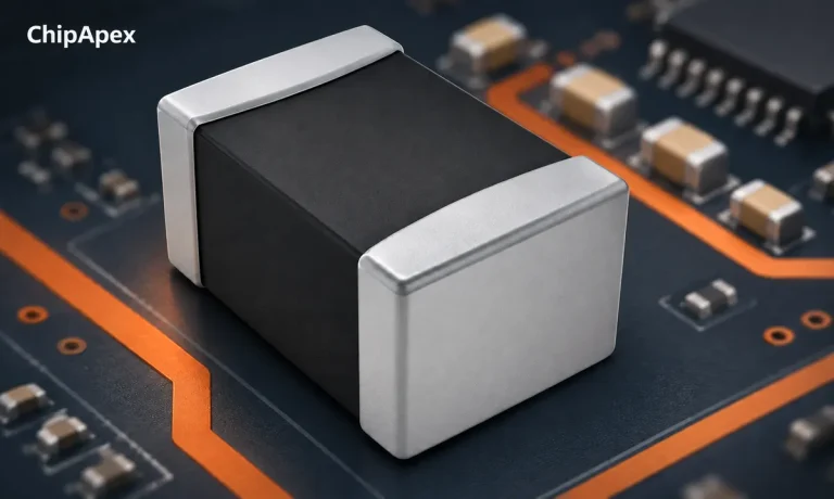
Learn how to use ferrite beads for noise filtering. Check impedance, DC bias, placement, resonance and load-step behavior before selecting a part.
Read More
SN74LV126APWRG4 is listed in the Buffers, Drivers, Receivers, Transceivers range at ChipApex. The manufacturer field lists Texas Instruments. Its product description is IC BUF…
Read More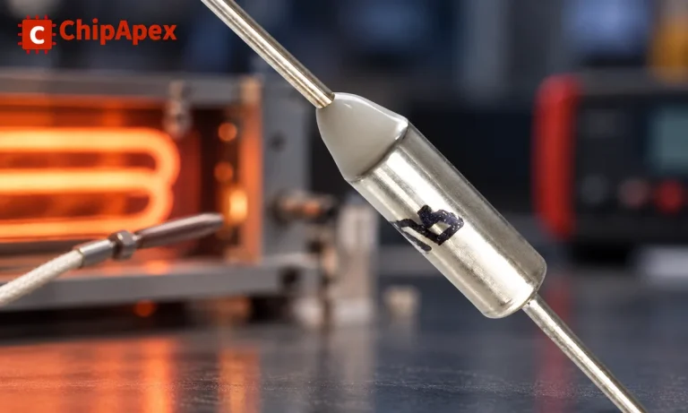
Understand thermal fuse operation, Tf, Th and Tm, electrical ratings and mounting. Check temperature limits and replacement requirements for your design.
Read More
SN74LV126APWRG4 is listed in the Buffers, Drivers, Receivers, Transceivers range at ChipApex. The manufacturer field lists Texas Instruments. Its product description is IC BUF…
Read More
SN74LV126APWRG4 is listed in the Buffers, Drivers, Receivers, Transceivers range at ChipApex. The manufacturer field lists Texas Instruments. Its product description is IC BUF…
Read More
SN74LV126APWRG4 is listed in the Buffers, Drivers, Receivers, Transceivers range at ChipApex. The manufacturer field lists Texas Instruments. Its product description is IC BUF…
Read More
SN74LV126APWRG4 is listed in the Buffers, Drivers, Receivers, Transceivers range at ChipApex. The manufacturer field lists Texas Instruments. Its product description is IC BUF…
Read More
SN74LV126APWRG4 is listed in the Buffers, Drivers, Receivers, Transceivers range at ChipApex. The manufacturer field lists Texas Instruments. Its product description is IC BUF…
Read More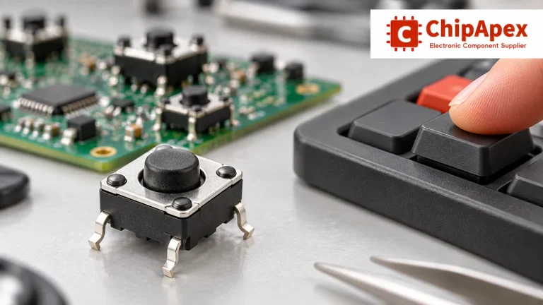
Understand tactile switches, PCB and keyboard differences, four-pin wiring, debounce, force, travel and replacement checks for reliable control inputs.
Read More
The activity of extra discounts on wholesale prices is in full swing…
Please fill in your contact information and we will send you the latest wholesale price list.





