 ChipApex | Global Electronic Components Supplier

SEARCH
Search Product
Search Post
— IC芯片 | 连接器 | 传感器 | 被动器件 —
Search productSearch post
— IC芯片 | 连接器 | 传感器 | 被动器件 —
Consult the customer manager about the wholesale price.
consultation hotline:86-132-6715-2157
email:[email protected]
Contact the product manager for consultation. One-stop consultation is available.
Do you want a lower wholesale price? Please send us your inquiry and we will reply immediately.
SN74LVC125APWR is listed in the Buffers, Drivers, Receivers, Transceivers range at ChipApex. The manufacturer field lists Texas Instruments. Its product description is IC BUF NON-INVERT 3.6V 14TSSOP. Review the specifications below when checking this part for your BOM.
The SN74LVC125APWR is a quadruple bus buffer gate with 3-state outputs manufactured by Texas Instruments. It operates from a supply voltage of 1.65V to 3.6V and features independent output-enable inputs for each buffer. The device accepts input voltages up to 5.5V, allowing compatibility with 3.3V or 5V logic systems. It is housed in a 14-pin TSSOP package and supports operating temperatures ranging from -40°C to 85°C and -40°C to 125°C.
Verify the specific ordering suffix 'PWR' corresponds to the TSSOP-14 package configuration required for your design. Confirm the temperature grade matches your environmental specifications, as variants exist for different thermal ranges. Ensure the component meets RoHS compliance standards applicable to your region before finalizing procurement.
Select this component when designing circuits requiring level translation between 3.3V and 5V logic domains. It is suitable for applications needing independent control over multiple signal lines via separate OE pins. Consider the low power consumption and fast switching characteristics for high-speed data bus buffering tasks.
This part belongs to the SN74LVC125A family of quadruple bus buffer gates. It is designed for low-voltage CMOS applications, offering robust performance in portable and battery-powered devices. The device ensures proper high-impedance states during power-up or power-down conditions when configured correctly.
SN74LVC125ADBR
To ensure the high-impedance state during power up or power down, the OE input should be tied to VCC through a pullup resistor.
Inputs accept voltages up to 5.5V, allowing the device to be driven by either 3.3V or 5V devices.
Explore related parts through Logic, Integrated Circuits (ICs), all product categories, ChipApex homepage.
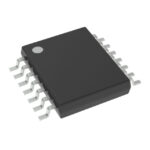 SN74LVC125APWR
SN74LVC125APWR is listed in the Buffers, Drivers, Receivers, Transceivers range at ChipApex. The manufacturer field lists Texas Instruments. Its product description is IC BUF…
Read More
SN74LVC125APWR is listed in the Buffers, Drivers, Receivers, Transceivers range at ChipApex. The manufacturer field lists Texas Instruments. Its product description is IC BUF…
Read More
SN74LVC125APWR is listed in the Buffers, Drivers, Receivers, Transceivers range at ChipApex. The manufacturer field lists Texas Instruments. Its product description is IC BUF…
Read More
SN74LVC125APWR is listed in the Buffers, Drivers, Receivers, Transceivers range at ChipApex. The manufacturer field lists Texas Instruments. Its product description is IC BUF…
Read More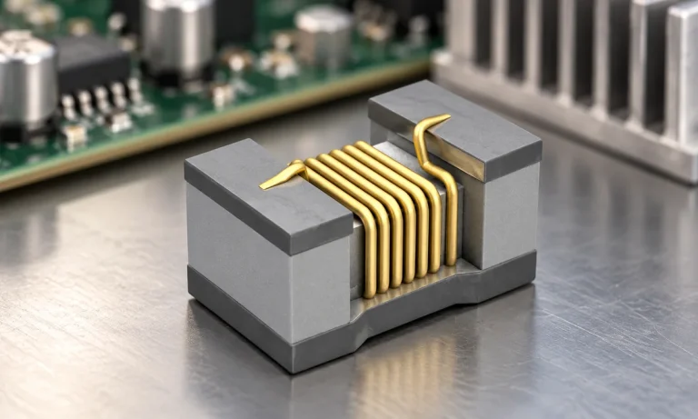
See when an inductor behaves linearly, how DC bias and saturation reduce inductance, and which current and temperature curves to check.
Read More
SN74LVC125APWR is listed in the Buffers, Drivers, Receivers, Transceivers range at ChipApex. The manufacturer field lists Texas Instruments. Its product description is IC BUF…
Read More
SN74LVC125APWR is listed in the Buffers, Drivers, Receivers, Transceivers range at ChipApex. The manufacturer field lists Texas Instruments. Its product description is IC BUF…
Read More
Find out when a bare shock switch needs a pull resistor, when an MCU internal pull-up is enough, and why sensor modules and piezo…
Read More
SN74LVC125APWR is listed in the Buffers, Drivers, Receivers, Transceivers range at ChipApex. The manufacturer field lists Texas Instruments. Its product description is IC BUF…
Read More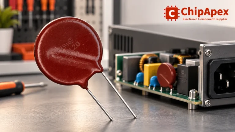
Select MOV varistors by continuous voltage, clamping behavior, surge waveform and repetition. Check thermal disconnection, fuse coordination and replacements.
Read More
SN74LVC125APWR is listed in the Buffers, Drivers, Receivers, Transceivers range at ChipApex. The manufacturer field lists Texas Instruments. Its product description is IC BUF…
Read More
SN74LVC125APWR is listed in the Buffers, Drivers, Receivers, Transceivers range at ChipApex. The manufacturer field lists Texas Instruments. Its product description is IC BUF…
Read More
The activity of extra discounts on wholesale prices is in full swing…
Please fill in your contact information and we will send you the latest wholesale price list.





