ChipApex | Global Electronic Components Supplier

SEARCH
Search Product
Search Post
— IC芯片 | 连接器 | 传感器 | 被动器件 —
Search productSearch post
— IC芯片 | 连接器 | 传感器 | 被动器件 —
Consult the customer manager about the wholesale price.
consultation hotline:86-132-6715-2157
email:[email protected]
Contact the product manager for consultation. One-stop consultation is available.
Do you want a lower wholesale price? Please send us your inquiry and we will reply immediately.
SN74S00NS is listed in the Inverter Gates range at ChipApex. The manufacturer field lists Texas Instruments. Its product description is IC GATE NAND. Review the specifications below when checking this part for your BOM.
The SN74S00NS is a quadruple 2-input positive-NAND gate from the Texas Instruments S series, housed in a 14-pin Small Outline (SO) package. It operates within a supply voltage range of 4.75 V to 5.25 V and supports an operating temperature range of 0°C to 70°C. The device features TTL-compliant inputs with VIH = 2 V and VIL = 0.8 V, allowing compatibility with 3.3-V or 2.5-V logic levels. Electrical characteristics include a low-level output current of 20 mA and a high-level output current of -1 mA. Switching performance specifies a typical propagation delay of 4.5 ns at 5 V with 15 pF load capacitance.
Verify the specific ordering suffix 'NS' corresponds to the Small Outline package variant rather than other package types like PDIP or SOIC. Confirm the device status is appropriate for the design lifecycle, as some S-series variants may be marked as not recommended for new designs. Ensure the procurement source provides valid RoHS compliance documentation and matches the manufacturer's official part number specifications.
Select this component when high-speed NAND logic is required within standard TTL voltage constraints. The S series offers faster propagation delays compared to LS or HC counterparts but consumes higher quiescent current. Verify that the application environment remains within the specified 0°C to 70°C temperature range and that the power supply stability adheres to the 4.75 V to 5.25 V limits for reliable operation.
This device belongs to the SNx4xx00 family of quadruple 2-input positive-NAND gates, which also includes SN7400 and SN74LS00 variants. The SN74S00NS specifically utilizes the S series technology, distinguishing it from the standard TTL and Low-Power Schottky versions by offering improved speed at the cost of increased power consumption. It shares the same logical function and pinout configuration across the family.
SN74S00N
Yes, the datasheet specifies that the inputs can accept 3.3-V or 2.5-V logic inputs while remaining TTL compliant.
No voltage greater than 5.5 V must be applied to the inputs, as exceeding this limit may cause the base-emitter junction at the inputs to break down.
Explore related parts through Logic, Integrated Circuits (ICs), all product categories, ChipApex homepage.
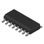 SN74S00NS
Choose logic inverter ICs by thresholds, supply, output drive and delay. Compare standard and Schmitt-trigger inputs, power sequencing and replacement checks.
Read More
SN74S00NS is listed in the Inverter Gates range at ChipApex. The manufacturer field lists Texas Instruments. Its product description is IC GATE NAND. Review…
Read More
Learn how a diode conducts, how to identify anode and cathode, and when to choose rectifier, TVS, Zener or photodiode types for a circuit.
Read More
SN74S00NS is listed in the Inverter Gates range at ChipApex. The manufacturer field lists Texas Instruments. Its product description is IC GATE NAND. Review…
Read More
SN74S00NS is listed in the Inverter Gates range at ChipApex. The manufacturer field lists Texas Instruments. Its product description is IC GATE NAND. Review…
Read More
SN74S00NS is listed in the Inverter Gates range at ChipApex. The manufacturer field lists Texas Instruments. Its product description is IC GATE NAND. Review…
Read More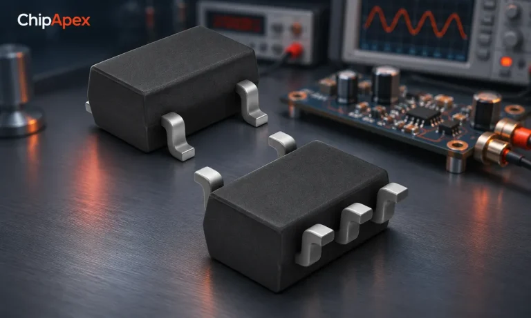
Learn how a JFET works and how to compare bias, leakage, noise and pinout. Review practical selection questions for high-impedance analog circuits.
Read More
SN74S00NS is listed in the Inverter Gates range at ChipApex. The manufacturer field lists Texas Instruments. Its product description is IC GATE NAND. Review…
Read More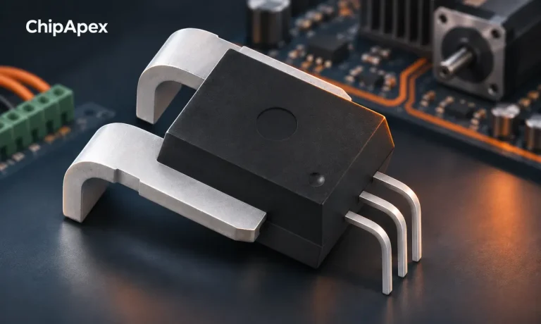
Compare Hall, shunt, current transformer and Rogowski sensing. Check AC/DC capability, accuracy, isolation, heat and response before selecting a sensor.
Read More
SN74S00NS is listed in the Inverter Gates range at ChipApex. The manufacturer field lists Texas Instruments. Its product description is IC GATE NAND. Review…
Read More
SN74S00NS is listed in the Inverter Gates range at ChipApex. The manufacturer field lists Texas Instruments. Its product description is IC GATE NAND. Review…
Read More
SN74S00NS is listed in the Inverter Gates range at ChipApex. The manufacturer field lists Texas Instruments. Its product description is IC GATE NAND. Review…
Read More
The activity of extra discounts on wholesale prices is in full swing…
Please fill in your contact information and we will send you the latest wholesale price list.