ChipApex | Global Electronic Components Supplier

SEARCH
Search Product
Search Post
— IC芯片 | 连接器 | 传感器 | 被动器件 —
Search productSearch post
— IC芯片 | 连接器 | 传感器 | 被动器件 —
Consult the customer manager about the wholesale price.
consultation hotline:86-132-6715-2157
email:[email protected]
Contact the product manager for consultation. One-stop consultation is available.
Do you want a lower wholesale price? Please send us your inquiry and we will reply immediately.
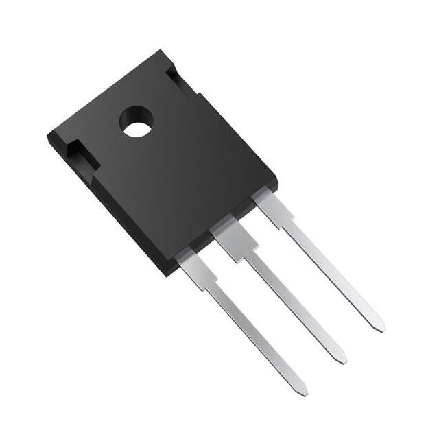
TRS30N120HB,S1Q is listed in the Diode Arrays range at ChipApex. The manufacturer field lists Toshiba Semiconductor and Storage. Its product description is 1200V30A SIC SCHOTTKY BARR DIODE. Review the specifications below when checking this part for your BOM.
The TRS30N120HB,S1Q is a silicon carbide Schottky barrier diode manufactured by Toshiba. It features a common anode configuration with two legs in a TO-247 package. The device supports a repetitive peak reverse voltage of 1200 V and a forward DC current of 15 A per leg or 30 A for both legs at Tc = 150 °C. Key electrical parameters include a typical forward voltage of 1.27 V, a total capacitive charge of 80 nC per leg, and a reverse current of 1.4 µA. It operates within a junction temperature range of -55 °C to +175 °C.
Verify the specific ordering suffix against official Toshiba documentation to confirm environmental compliance status and marking details. Confirm thermal management requirements align with the specified junction-to-case thermal resistance values. Ensure application designs account for the absolute maximum ratings provided in the datasheet to maintain long-term reliability under heavy loads.
Select this component for high-efficiency power conversion circuits requiring low switching losses and robust surge handling. The dual-leg common anode structure simplifies circuit topology for center-tapped or bridge configurations. Evaluate thermal dissipation needs based on the specified power dissipation limits and thermal resistance characteristics for the target operating environment.
This part belongs to the Toshiba TRSx series of silicon carbide Schottky barrier diodes. These devices utilize wide band-gap material technology to achieve high voltage ratings and improved performance compared to traditional silicon rectifiers. The series is designed for modern power electronics applications demanding higher efficiency and compact form factors.
Consult official Toshiba substitution guides for verified equivalents. Cross-referencing with other manufacturers requires careful validation of pinout compatibility, thermal characteristics, and electrical ratings to ensure system integrity.
The device features a common anode configuration with two independent cathodes (legs) housed in a single TO-247 package.
The third-generation design enables lower forward voltage, reduced total capacitive charge, and minimized reverse current compared to previous generations.
The junction temperature range is -55 °C to +175 °C, with storage temperatures spanning the same range.
Explore related parts through Rectifiers, Diodes, Discrete Semiconductor Products, all product categories.
 TRS30N120HB,S1Q

TRS30N120HB,S1Q is listed in the Diode Arrays range at ChipApex. The manufacturer field lists Toshiba Semiconductor and Storage. Its product description is 1200V30A SIC…
Read More
TRS30N120HB,S1Q is listed in the Diode Arrays range at ChipApex. The manufacturer field lists Toshiba Semiconductor and Storage. Its product description is 1200V30A SIC…
Read More
TRS30N120HB,S1Q is listed in the Diode Arrays range at ChipApex. The manufacturer field lists Toshiba Semiconductor and Storage. Its product description is 1200V30A SIC…
Read More
TRS30N120HB,S1Q is listed in the Diode Arrays range at ChipApex. The manufacturer field lists Toshiba Semiconductor and Storage. Its product description is 1200V30A SIC…
Read More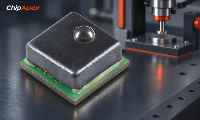
Understand load cell sensor output, bridge wiring and calibration. Learn how mV/V sensitivity, mechanics and ADC noise affect measurement accuracy.
Read More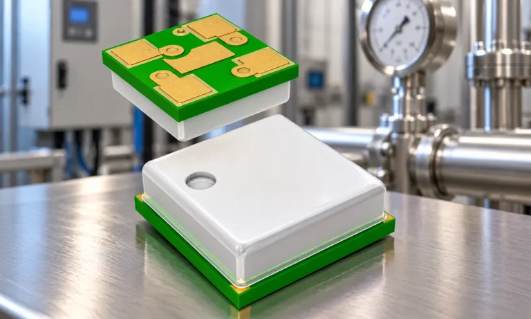
Learn how a pressure transducer converts pressure into voltage, current, or digital output, and compare pressure references and key selection specs.
Read More
TRS30N120HB,S1Q is listed in the Diode Arrays range at ChipApex. The manufacturer field lists Toshiba Semiconductor and Storage. Its product description is 1200V30A SIC…
Read More
TRS30N120HB,S1Q is listed in the Diode Arrays range at ChipApex. The manufacturer field lists Toshiba Semiconductor and Storage. Its product description is 1200V30A SIC…
Read More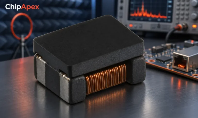
Select a common mode choke using noise frequency, current, insulation and signal integrity. Understand impedance curves, layout and filter limitations.
Read More
TRS30N120HB,S1Q is listed in the Diode Arrays range at ChipApex. The manufacturer field lists Toshiba Semiconductor and Storage. Its product description is 1200V30A SIC…
Read More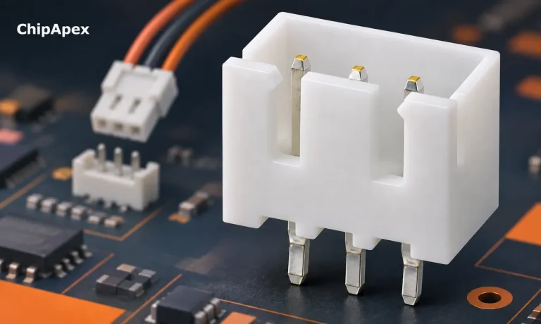
Choose a pin header by pitch, mating geometry, current rating and mounting. Learn why matching pin count and spacing does not guarantee compatibility.
Read More
TRS30N120HB,S1Q is listed in the Diode Arrays range at ChipApex. The manufacturer field lists Toshiba Semiconductor and Storage. Its product description is 1200V30A SIC…
Read More
The activity of extra discounts on wholesale prices is in full swing…
Please fill in your contact information and we will send you the latest wholesale price list.