 ChipApex | Global Electronic Components Supplier

SEARCH
Search Product
Search Post
— IC芯片 | 连接器 | 传感器 | 被动器件 —
Search productSearch post
— IC芯片 | 连接器 | 传感器 | 被动器件 —
Consult the customer manager about the wholesale price.
consultation hotline:86-132-6715-2157
email:[email protected]
Contact the product manager for consultation. One-stop consultation is available.
Do you want a lower wholesale price? Please send us your inquiry and we will reply immediately.
UCC27425PE4 is listed in the Gate Driver range at ChipApex. The manufacturer field lists Texas Instruments. Its product description is IC GATE DRVR LOW-SIDE 8DIP. Review the specifications below when checking this part for your BOM.
The UCC27425PE4 is a dual low-side MOSFET gate driver from Texas Instruments, housed in an 8-pin PDIP package. It provides one inverting and one non-inverting output channel with a peak drive current of ±4 A. The device operates on a supply voltage range of 4 V to 15 V and supports CMOS logic inputs independent of the supply voltage. Typical switching performance includes a 20 ns rise time and a 15 ns fall time under a 1.8-nF load. It features dedicated enable pins for each driver and is rated for operation between -40°C and +105°C.
Verify the specific suffix 'E4' against the manufacturer's official documentation to confirm RoHS compliance status and material composition details. Ensure the selected package variant matches the required PCB footprint and thermal management strategy for the target application environment.
Select this component when a mixed polarity configuration (one inverting, one non-inverting) is required within a single package. The ±4 A drive current is suitable for medium-power MOSFETs, while the wide supply voltage range accommodates various logic levels. Consider the PDIP package constraints regarding thermal dissipation compared to surface-mount alternatives.
The UCC27425PE4 belongs to the UCC2742x family of high-speed dual MOSFET drivers. This series offers industry-standard pin-outs with added enable functionality. The family includes variants with dual-inverting, dual-non-inverting, and mixed configurations, all sharing similar electrical characteristics and packaging options such as SOIC-8 and MSOP.
UCC27425P
The enable functions are implemented on pins 1 and 8, which are internally pulled up to Vdd for active-high logic. These pins can be left open for standard operation.
The typical propagation delay times are 25 ns with input falling and 35 ns with input rising.
Explore related parts through Power Management (PMIC), Integrated Circuits (ICs), all product categories, ChipApex homepage.
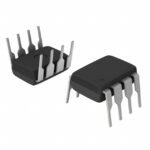 UCC27425PE4
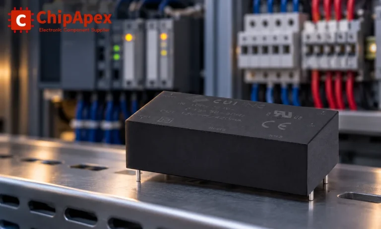
Choose an AC to DC converter by input range, output demand, isolation, efficiency and thermal derating. Compare architectures and check installation needs.
Read MoreUCC27425PE4 is listed in the Gate Driver range at ChipApex. The manufacturer field lists Texas Instruments. Its product description is IC GATE DRVR LOW-SIDE…
Read More
UCC27425PE4 is listed in the Gate Driver range at ChipApex. The manufacturer field lists Texas Instruments. Its product description is IC GATE DRVR LOW-SIDE…
Read More
UCC27425PE4 is listed in the Gate Driver range at ChipApex. The manufacturer field lists Texas Instruments. Its product description is IC GATE DRVR LOW-SIDE…
Read More
UCC27425PE4 is listed in the Gate Driver range at ChipApex. The manufacturer field lists Texas Instruments. Its product description is IC GATE DRVR LOW-SIDE…
Read More
UCC27425PE4 is listed in the Gate Driver range at ChipApex. The manufacturer field lists Texas Instruments. Its product description is IC GATE DRVR LOW-SIDE…
Read More
UCC27425PE4 is listed in the Gate Driver range at ChipApex. The manufacturer field lists Texas Instruments. Its product description is IC GATE DRVR LOW-SIDE…
Read More
UCC27425PE4 is listed in the Gate Driver range at ChipApex. The manufacturer field lists Texas Instruments. Its product description is IC GATE DRVR LOW-SIDE…
Read More
UCC27425PE4 is listed in the Gate Driver range at ChipApex. The manufacturer field lists Texas Instruments. Its product description is IC GATE DRVR LOW-SIDE…
Read More
UCC27425PE4 is listed in the Gate Driver range at ChipApex. The manufacturer field lists Texas Instruments. Its product description is IC GATE DRVR LOW-SIDE…
Read More
UCC27425PE4 is listed in the Gate Driver range at ChipApex. The manufacturer field lists Texas Instruments. Its product description is IC GATE DRVR LOW-SIDE…
Read More
UCC27425PE4 is listed in the Gate Driver range at ChipApex. The manufacturer field lists Texas Instruments. Its product description is IC GATE DRVR LOW-SIDE…
Read More
The activity of extra discounts on wholesale prices is in full swing…
Please fill in your contact information and we will send you the latest wholesale price list.







