 ChipApex | Global Electronic Components Supplier

SEARCH
Search Product
Search Post
— IC芯片 | 连接器 | 传感器 | 被动器件 —
Search productSearch post
— IC芯片 | 连接器 | 传感器 | 被动器件 —
The trend of science and technology is changing rapidly.
A limit switch detects a defined mechanical position when a moving object operates its actuator. The switch changes an electrical contact state, allowing a controller to recognize travel, position or an end point. Reliable operation depends on actuator geometry, permitted movement, contact loading and installation conditions.
For a machine builder, the first question is where the switch must change state during the mechanism's movement. Compare limit switches after defining that position and the distance the mechanism can continue moving. The switch's operating point and its mechanical travel limit serve different purposes.
An actuator transfers motion to an internal switching mechanism. A plunger moves directly into the body, while a lever or roller converts an external movement into travel at the mechanism. The resulting contacts can signal a controller, operate an appropriate relay circuit or switch a suitable load.
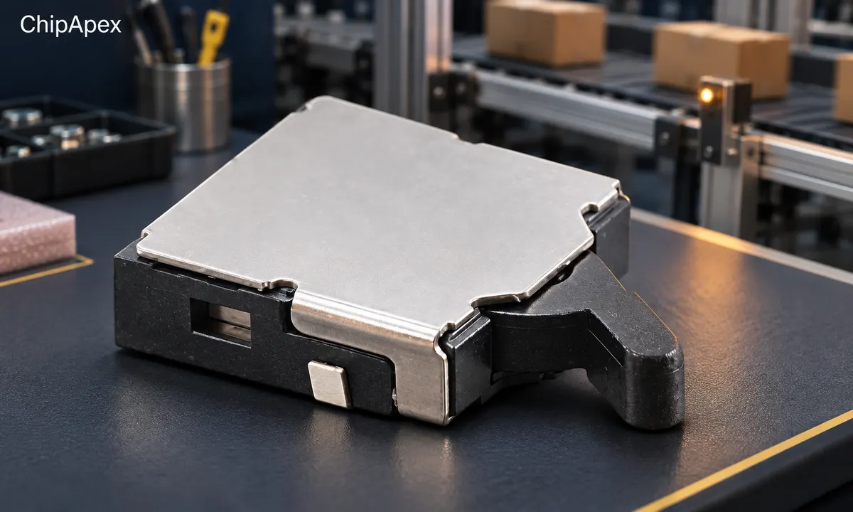
On a conveyor, a passing item might move a roller lever and create an input event. On a slide, a cam may operate the switch near the end of travel. The controller's response, including braking distance and processing delay, determines where the machine finally stops. The switch detects position at its actuator.
Contact-based sensing requires physical interaction. A proximity sensor uses another detection mechanism, such as an inductive or optical field. Selection between them depends on the target, required accuracy, environment and permitted contact force. A contact device can be useful where the position is mechanically well defined, while repeated impacts and wear need attention.
The actuator should follow the direction and shape of the moving part without excessive side load. Selection includes approach angle, speed, available stroke and the force the mechanism can provide. The manufacturer's actuator selection guide compares these operating characteristics across constructions.
| Actuator | Typical movement | Design check |
|---|---|---|
| Direct plunger | Controlled axial approach | Alignment, short stroke and permitted force |
| Roller plunger | Cam or sliding approach | Cam profile and roller loading |
| Roller lever | Cam or passing object | Lever angle, approach direction and travel |
| Flexible rod or whisker | Deflection over a wider approach area | Detection consistency and permitted deflection |
Package size alone gives little information about these limits. A compact switch on a PCB and a sealed industrial lever switch can share the same basic operating principle while requiring very different mounting and load conditions.
Consider the complete cycle. The mechanism must operate the switch reliably, remain within its allowed travel, then release it far enough for the contacts to reset. A cam that works during a slow hand test may produce bounce, impact or excessive travel at production speed.
Pretravel is the movement from the free position to the operating position. Overtravel is the permitted movement beyond operation toward the specified total-travel limit. Differential travel describes the movement between operation and release. Read the selected device's drawing because units may be millimeters or degrees.
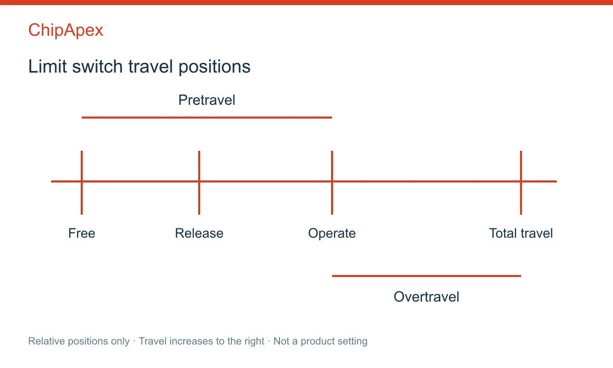
Allow enough movement to operate the contacts under real tolerances. Include variation in the mounting bracket, cam, bearings, temperature and switch operating point. At the same time, prevent the mechanism from forcing the actuator past its allowed travel.
A separate mechanical stop can limit machine movement where required. Its position must account for the switch and machine dynamics. Manufacturer limit-switch application guidance discusses actuator loading and overtravel restrictions. Use the selected model's limits for the final setting.
Repeatability also differs from absolute operating-point accuracy. A device can switch consistently over repeated cycles while its nominal operating position has a production tolerance. Decide whether the application needs a repeatable event, an accurate coordinate or both.
Normally open and normally closed describe the contact state with the actuator in its specified normal position. Verify the terminal diagram and contact sequence. A changeover contact does not imply that both outputs can be treated as independent, simultaneous signals.
For a PLC input, check the input voltage, expected current and minimum switching load. A switch designed for substantial power may have different contact material and low-level behavior from a signal contact. Very small currents can make contamination or contact resistance more significant.
For a motor, solenoid or contactor coil, evaluate the load-specific making and breaking ratings. The steady current does not describe starting current or the energy interrupted when an inductive load turns off. Suitable relays or another driver stage may be required between a position switch and the controlled load.
Contact bounce can produce several transitions from one operation. The controller may need input filtering or debounce, with the resulting delay included in the position and stopping calculations. Excessive filtering can hide a short event.
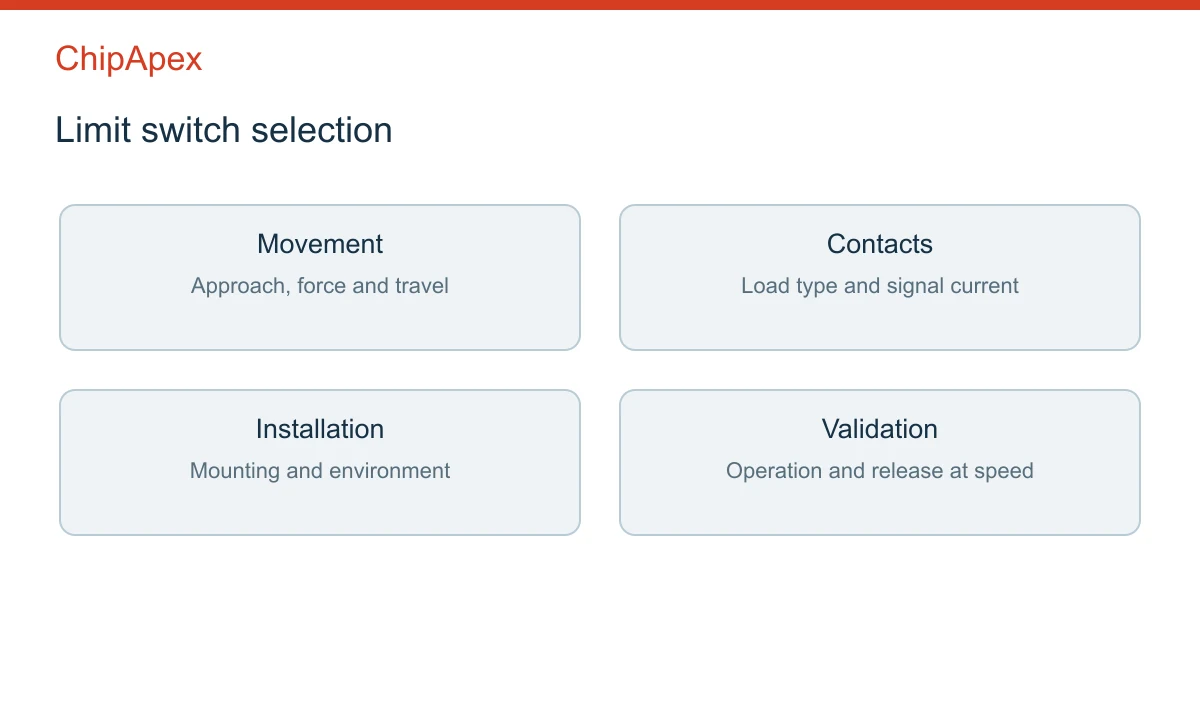
Check mounting rigidity, cable entry, enclosure protection and the expected oil, coolant, dust or moisture exposure. A protection rating applies under stated assembly conditions. Cable seals and terminal covers are part of the installation.
An intermittent signal may come from loose mounting, insufficient travel, contact contamination, wiring faults or electrical noise. Start with a controlled observation of actuator motion and the corresponding input state. Compare operation and release in both directions where the mechanism permits it.
If a switch works when pressed by hand but fails in the machine, inspect approach geometry and speed. If the contacts change correctly but the controller misses the event, check pulse duration, input thresholds, filtering and scan timing. These checks help distinguish a mechanical operating problem from a signal-processing problem.
Specify actuator type, operating position tolerance, travel, contact form, switching voltage and load, mounting dimensions, environment and expected cycle rate. For a replacement, include the original part number and drawing. The broader switches category can help identify another construction when the mechanism requires a different interface.
Send ChipApex these requirements with the quantity and acceptable package constraints. Request the exact datasheet when evaluating alternatives, including any required direct-opening or safety-related properties. Those properties depend on the approved component and complete machine design.
It can switch a motor only when its ratings and circuit design support that duty. Many applications use the contact as a controller input or to operate a separate switching stage. Check motor startup current, interruption conditions and the machine's required response before choosing the arrangement.
A microswitch commonly refers to a compact snap-action switching mechanism. A limit switch describes a position-detection function and often includes an actuator and protective enclosure around a switching mechanism. Some compact products fit both descriptions. Confirm the construction and operating conditions from the drawing.
The choice depends on the input circuit, normal operating state and required fault detection. A normally closed loop can reveal some open-circuit faults, but it does not detect every failure. Contact form alone cannot establish the safety performance of a machine function.
Check the permitted operating-point tolerance, approach direction, lever adjustment, mounting movement and wear. Temperature and the mechanism's speed may also affect the observed result. Measure the actuator position consistently and distinguish switch variation from movement elsewhere in the assembly.
Compare contact form, terminal assignment, operating and release positions, travel limits, actuator force, ratings and enclosure requirements. A matching housing outline may still conceal different mechanics. For an existing machine, evaluate the complete operating cycle with the proposed replacement.
Learn how a thermostat in a heater works. Check hysteresis, reset mode, thermal placement and contact ratings before selecting a mechanical control.
View details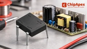
Select a bridge rectifier by reverse voltage, capacitor charging current, startup surge and cooling. Work through a stated DC voltage and ripple example.
View details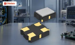
Understand how oscillators generate timing signals, how they differ from crystals, and which frequency, output and stability specs matter when choosing one.
View details
Compare variable capacitor types and varactor tuning. Understand capacitance-voltage curves, Q, bias and LC resonance before choosing a component.
View details
The activity of extra discounts on wholesale prices is in full swing…
Please fill in your contact information and we will send you the latest wholesale price list.

