 ChipApex | Global Electronic Components Supplier

SEARCH
Search Product
Search Post
— IC芯片 | 连接器 | 传感器 | 被动器件 —
Search productSearch post
— IC芯片 | 连接器 | 传感器 | 被动器件 —
Consult the customer manager about the wholesale price.
consultation hotline:86-132-6715-2157
email:[email protected]
Contact the product manager for consultation. One-stop consultation is available.
Do you want a lower wholesale price? Please send us your inquiry and we will reply immediately.
74ACT16657DL is listed in the Buffers, Drivers, Receivers, Transceivers range at ChipApex. The manufacturer field lists Texas Instruments. Its product description is IC TXRX NON-INVERT 5.5V 56SSOP. Review the specifications below when checking this part for your BOM.
The Texas Instruments 74ACT16657DL is a 16-bit transceiver featuring integrated parity generators and checkers with 3-state outputs. It contains two noninverting octal transceiver sections, each equipped with separate parity control circuits. The device utilizes the Widebus architecture to optimize PCB layout and includes distributed VCC and GND pins to minimize high-speed switching noise. It operates within a supply voltage range of 4.5 V to 5.5 V and supports TTL-voltage compatible inputs.
Verify the specific package variant (DL) against the required footprint dimensions. Confirm RoHS compliance status and lead finish specifications for soldering compatibility. Ensure the operating temperature range meets the environmental requirements of the target application design.
Select this component when designing systems that require simultaneous data transfer and parity checking without external logic. Consider the 56-pin SSOP package constraints and the 4.5 V to 5.5 V supply voltage requirement. Evaluate the propagation delay characteristics against the system clock speed to ensure timing margins are met.
This part belongs to the 74ACT logic family, utilizing EPIC technology for enhanced performance. It is part of the Widebus family, designed to provide higher I/O density in standard small-outline packages compared to traditional logic families.
Check datasheets for SN74ACT16657 or 54ACT16657 variants to confirm functional equivalence and temperature range suitability before substitution.
In transmit mode, the parity generator calculates the bit value based on the input bus. In receive mode, the checker compares the received parity bit against the calculated value to set the ERR output.
The direction is controlled by the T/R input; a high level enables transmit mode (A to B), while a low level enables receive mode (B to A).
Explore related parts through Logic, Integrated Circuits (ICs), all product categories, ChipApex homepage.
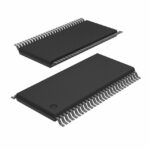 74ACT16657DL
Learn what an integrated circuit is, how ICs work, the main types and the specs to check before choosing a part for your design…
Read More
74ACT16657DL is listed in the Buffers, Drivers, Receivers, Transceivers range at ChipApex. The manufacturer field lists Texas Instruments. Its product description is IC TXRX…
Read More
74ACT16657DL is listed in the Buffers, Drivers, Receivers, Transceivers range at ChipApex. The manufacturer field lists Texas Instruments. Its product description is IC TXRX…
Read More
74ACT16657DL is listed in the Buffers, Drivers, Receivers, Transceivers range at ChipApex. The manufacturer field lists Texas Instruments. Its product description is IC TXRX…
Read More
74ACT16657DL is listed in the Buffers, Drivers, Receivers, Transceivers range at ChipApex. The manufacturer field lists Texas Instruments. Its product description is IC TXRX…
Read More
74ACT16657DL is listed in the Buffers, Drivers, Receivers, Transceivers range at ChipApex. The manufacturer field lists Texas Instruments. Its product description is IC TXRX…
Read More
Learn why PTC resistance rises with temperature, how it differs from NTC, and which ratings matter for sensing and protection.
Read More
74ACT16657DL is listed in the Buffers, Drivers, Receivers, Transceivers range at ChipApex. The manufacturer field lists Texas Instruments. Its product description is IC TXRX…
Read More
See when an inductor behaves linearly, how DC bias and saturation reduce inductance, and which current and temperature curves to check.
Read More
74ACT16657DL is listed in the Buffers, Drivers, Receivers, Transceivers range at ChipApex. The manufacturer field lists Texas Instruments. Its product description is IC TXRX…
Read More
74ACT16657DL is listed in the Buffers, Drivers, Receivers, Transceivers range at ChipApex. The manufacturer field lists Texas Instruments. Its product description is IC TXRX…
Read More
Understand how a comparator switches at a voltage threshold, why hysteresis prevents chatter, and which output and input specs matter.
Read More
The activity of extra discounts on wholesale prices is in full swing…
Please fill in your contact information and we will send you the latest wholesale price list.





