 ChipApex | Global Electronic Components Supplier

SEARCH
Search Product
Search Post
— IC芯片 | 连接器 | 传感器 | 被动器件 —
Search productSearch post
— IC芯片 | 连接器 | 传感器 | 被动器件 —
Consult the customer manager about the wholesale price.
consultation hotline:86-132-6715-2157
email:[email protected]
Contact the product manager for consultation. One-stop consultation is available.
Do you want a lower wholesale price? Please send us your inquiry and we will reply immediately.
74AUP2G14FW4-7 is listed in the Inverter Gates range at ChipApex. The manufacturer field lists Diodes Incorporated. Its product description is IC INVERTER 2CH 2-INP DFN1010-6. Review the specifications below when checking this part for your BOM.
The 74AUP2G14FW4-7 is a dual Schmitt trigger inverter from the Advanced Ultra Low Power (AUP) CMOS logic family, manufactured by Diodes Incorporated. It operates within a supply voltage range of 0.8V to 3.6V and features standard push-pull outputs with ±4mA drive capability at 3.0V. The device incorporates I_OFF circuitry for partial power-down applications, preventing damaging current backflow. Static power consumption is low, with ICC less than 0.9µA, and typical dynamic power consumption capacitance (CPD) is 4pF at 3.6V. It is housed in an X2-DFN1010-6 package.
Verify the FW4 suffix corresponds to the X2-DFN1010-6 package configuration. Confirm RoHS compliance and lead-free status requirements against specific project constraints. Ensure ordering quantities align with the manufacturer's tape and reel specifications for this package type.
Select this component when low static and dynamic power consumption are critical alongside noise immunity provided by Schmitt triggers. The wide operating voltage range suits battery applications. Verify that the X2-DFN1010-6 package dimensions fit the available PCB space and thermal requirements.
This part belongs to the 74AUP2G series of dual-gate logic devices designed for ultra-low power portable electronics. The AUP family emphasizes extended battery life through reduced power consumption while maintaining robust signal integrity via Schmitt trigger inputs.
Check datasheets for other 74AUP2G14 variants with different package suffixes (DW, FW3, FZ4) if pinout compatibility or board space differs. Ensure any substitute maintains the same Schmitt trigger functionality and voltage range.
The I_OFF circuitry disables the output when the device is powered down, preventing damaging current backflow into the system.
It makes the circuit tolerant for slower input rise and fall times, improving noise immunity and signal stability.
Explore related parts through Logic, Integrated Circuits (ICs), all product categories, ChipApex homepage.
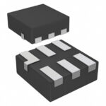 74AUP2G14FW4-7
74AUP2G14FW4-7 is listed in the Inverter Gates range at ChipApex. The manufacturer field lists Diodes Incorporated. Its product description is IC INVERTER 2CH 2-INP…
Read More
74AUP2G14FW4-7 is listed in the Inverter Gates range at ChipApex. The manufacturer field lists Diodes Incorporated. Its product description is IC INVERTER 2CH 2-INP…
Read More
74AUP2G14FW4-7 is listed in the Inverter Gates range at ChipApex. The manufacturer field lists Diodes Incorporated. Its product description is IC INVERTER 2CH 2-INP…
Read More
74AUP2G14FW4-7 is listed in the Inverter Gates range at ChipApex. The manufacturer field lists Diodes Incorporated. Its product description is IC INVERTER 2CH 2-INP…
Read More
Learn how a pressure transducer converts pressure into voltage, current, or digital output, and compare pressure references and key selection specs.
Read More
74AUP2G14FW4-7 is listed in the Inverter Gates range at ChipApex. The manufacturer field lists Diodes Incorporated. Its product description is IC INVERTER 2CH 2-INP…
Read More
74AUP2G14FW4-7 is listed in the Inverter Gates range at ChipApex. The manufacturer field lists Diodes Incorporated. Its product description is IC INVERTER 2CH 2-INP…
Read More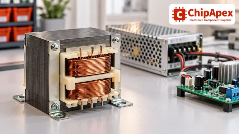
Select power transformers by input frequency, secondary VA, rectifier load, isolation, regulation and inrush. Build a clearer specification for your next RFQ.
Read More
74AUP2G14FW4-7 is listed in the Inverter Gates range at ChipApex. The manufacturer field lists Diodes Incorporated. Its product description is IC INVERTER 2CH 2-INP…
Read More
74AUP2G14FW4-7 is listed in the Inverter Gates range at ChipApex. The manufacturer field lists Diodes Incorporated. Its product description is IC INVERTER 2CH 2-INP…
Read More
74AUP2G14FW4-7 is listed in the Inverter Gates range at ChipApex. The manufacturer field lists Diodes Incorporated. Its product description is IC INVERTER 2CH 2-INP…
Read More
74AUP2G14FW4-7 is listed in the Inverter Gates range at ChipApex. The manufacturer field lists Diodes Incorporated. Its product description is IC INVERTER 2CH 2-INP…
Read More
The activity of extra discounts on wholesale prices is in full swing…
Please fill in your contact information and we will send you the latest wholesale price list.





