ChipApex | Global Electronic Components Supplier
AD8542ARZ
Search Product
Search Post
— IC芯片 | 连接器 | 传感器 | 被动器件 —
Search productSearch post
— IC芯片 | 连接器 | 传感器 | 被动器件 —
Consult the customer manager about the wholesale price.
consultation hotline:86-132-6715-2157
email:[email protected]
Contact the product manager for consultation. One-stop consultation is available.
Do you want a lower wholesale price? Please send us your inquiry and we will reply immediately.
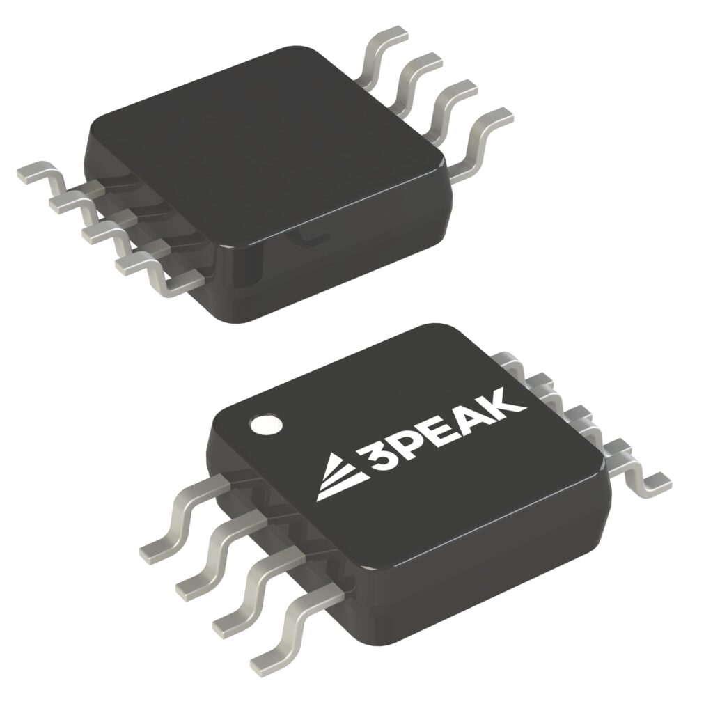
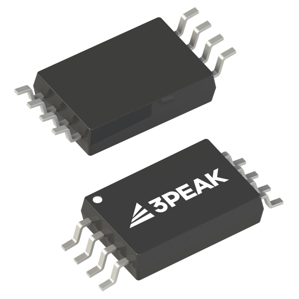
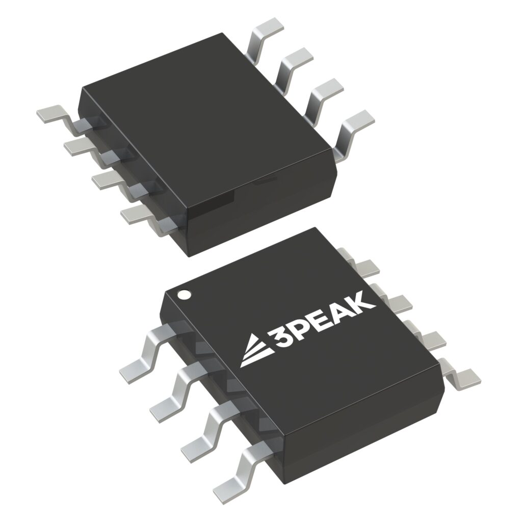
The AD8542ARZ is a dual-channel, low-voltage micro-power CMOS voltage feedback operational amplifier manufactured by UMW. It features a gain-bandwidth product of 1.1MHz and a slew rate of 0.8V/μs with a quiescent current of 85μA per amplifier at 5V. The device supports single or dual power supplies ranging from +2.3V to +5.5V and operates over an extended industrial temperature range of -40℃ to +125℃. Key electrical characteristics include a maximum input offset voltage of 3.5mV, very low input bias current of 1pA, and rail-to-rail input and output capabilities.
Verify that the component matches the UMW manufacturer specifications rather than Analog Devices equivalents. Confirm the package type corresponds to the required board layout, as the AD8542 is available in MSOP-8 and SOP-8 configurations. Ensure the operating environment stays within the specified -40℃ to +125℃ temperature range and supply voltage limits of 2.3V to 5.5V to maintain guaranteed performance parameters.
Select this component for general-purpose applications requiring optimal performance with low power consumption. The device is suitable for designs needing rail-to-rail signal handling and high gain stability. Consider PCB surface leakage effects due to the extremely low input bias current; guard rings are recommended for sensitive pins. Verify that capacitive loads do not compromise stability without isolation resistors.
This part belongs to the AD854x family, which includes the single-channel AD8541 and quad-channel AD8544 variants. All models share identical electrical characteristics and are designed for low voltage micro-power applications. The AD8542 specifically provides two amplifiers in an 8-lead package, making it ideal for compact dual-channel signal conditioning tasks.
Direct substitutes include the AD8541 (single channel) and AD8544 (quad channel) from the same series. Cross-manufacturer replacements must match the 1.1MHz bandwidth, 85μA quiescent current, and RRIO specifications while maintaining the 2.3V to 5.5V supply range.
Yes, the input common-mode voltage range extends 200mV beyond the supply rails. Inputs can go up to 400mV beyond the supplies without causing damage or phase inversion if input current is limited.
Use multi-layer PCB layouts and route signals under the surface. Implement guard rings biased at the same voltage as sensitive pins to reduce surface leakage caused by humidity or contamination.
A ceramic capacitor between 0.01μF and 0.1μF should be placed close to the power supply pin. For dual-supply operation, separate 0.1μF capacitors are recommended for each supply rail.
 AD8542ARZ
The activity of extra discounts on wholesale prices is in full swing…
Please fill in your contact information and we will send you the latest wholesale price list.