 ChipApex | Global Electronic Components Supplier

SEARCH
Search Product
Search Post
— IC芯片 | 连接器 | 传感器 | 被动器件 —
Search productSearch post
— IC芯片 | 连接器 | 传感器 | 被动器件 —
Consult the customer manager about the wholesale price.
consultation hotline:86-132-6715-2157
email:[email protected]
Contact the product manager for consultation. One-stop consultation is available.
Do you want a lower wholesale price? Please send us your inquiry and we will reply immediately.
ADS7800KUE4 is listed in the Analog To Digital Converters (ADC) range at ChipApex. The manufacturer field lists Texas Instruments. Its product description is 12-BIT 3US SAMPLING ANALOG-TO-DI. Review the specifications below when checking this part for your BOM.
The ADS7800KUE4 is a 12-bit successive approximation analog-to-digital converter manufactured by Texas Instruments. It operates with a throughput rate of 333 kS/s and features an internal sample/hold, reference, clock, and three-state outputs. The device supports standard ±10V and ±5V input ranges via selectable pins. It requires a +5V digital/analog supply and a –12V or –15V negative supply. Key electrical specifications include a maximum conversion time of 2.7 µs, integral linearity error of ±1/2 LSB, differential linearity error of ±3/4 LSB, and a signal-to-noise ratio of 73 dB. It is housed in a 24-lead SOIC package.
Verify the specific suffix 'KU' corresponds to the commercial grade (0°C to +70°C) rather than the extended temperature grade ('AH' or 'BH'). Confirm the package type matches the required PCB footprint for the 24-lead SOIC. Check for RoHS compliance status as indicated in the ordering information. Ensure power supply requirements align with the +5V and –12V/–15V specifications before integration.
Select this component when a high-speed 12-bit resolution with a 333 kS/s throughput is required. It is suitable for applications needing direct ±10V or ±5V inputs without external attenuation circuitry. Consider the internal reference and clock capabilities if board space for external components is limited. Evaluate the parallel interface requirement against available microprocessor data buses.
The ADS7800 series includes variants such as the ADS7800JP/JU/AH and ADS7800KP/KU/BH. The 'K' designation typically indicates the commercial temperature range, while 'J' may refer to other grades. The 'U' suffix denotes the SOIC package. Other packages include plastic DIP and side-braze hermetic ceramic options. The datasheet specifies performance across different temperature ranges for these variants.
Public confirmed substitute part numbers are not provided in the source material. Verify pin compatibility and electrical specifications carefully if considering alternative ADCs from other manufacturers.
Connect the analog signal to Pin 1 (IN1) for the ±10V range or Pin 2 (IN2) for the ±5V range. The unused input pin must be connected to ground.
The BUSY output goes LOW during the conversion period and rises HIGH when the conversion is complete and data is valid. It keeps the data outputs in a Hi-Z state during conversion.
Yes, by connecting CS and HBE to GND and controlling only the R/C input, the device can operate in a stand-alone mode where conversions are initiated by pulses on R/C.
Explore related parts through Data Acquisition, Integrated Circuits (ICs), all product categories, ChipApex homepage.
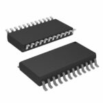 ADS7800KUE4

ADS7800KUE4 is listed in the Analog To Digital Converters (ADC) range at ChipApex. The manufacturer field lists Texas Instruments. Its product description is 12-BIT…
Read More
ADS7800KUE4 is listed in the Analog To Digital Converters (ADC) range at ChipApex. The manufacturer field lists Texas Instruments. Its product description is 12-BIT…
Read More
ADS7800KUE4 is listed in the Analog To Digital Converters (ADC) range at ChipApex. The manufacturer field lists Texas Instruments. Its product description is 12-BIT…
Read More
ADS7800KUE4 is listed in the Analog To Digital Converters (ADC) range at ChipApex. The manufacturer field lists Texas Instruments. Its product description is 12-BIT…
Read More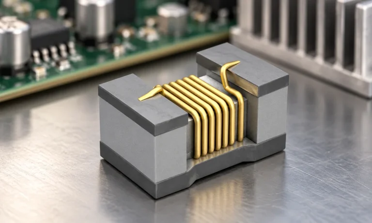
See when an inductor behaves linearly, how DC bias and saturation reduce inductance, and which current and temperature curves to check.
Read More
ADS7800KUE4 is listed in the Analog To Digital Converters (ADC) range at ChipApex. The manufacturer field lists Texas Instruments. Its product description is 12-BIT…
Read More
ADS7800KUE4 is listed in the Analog To Digital Converters (ADC) range at ChipApex. The manufacturer field lists Texas Instruments. Its product description is 12-BIT…
Read More
ADS7800KUE4 is listed in the Analog To Digital Converters (ADC) range at ChipApex. The manufacturer field lists Texas Instruments. Its product description is 12-BIT…
Read More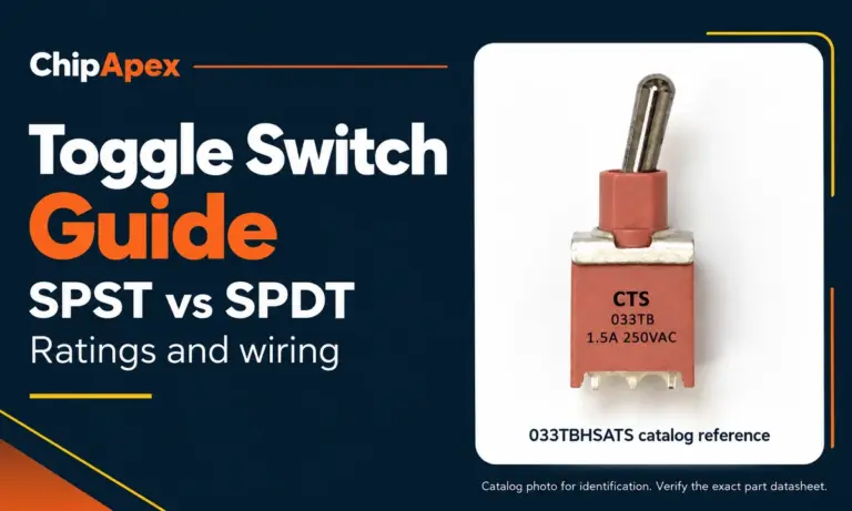
Compare SPST and SPDT toggle switches, understand AC/DC ratings, and follow wiring examples. Check contact action, mounting and parts in the ChipApex catalog.
Read More
ADS7800KUE4 is listed in the Analog To Digital Converters (ADC) range at ChipApex. The manufacturer field lists Texas Instruments. Its product description is 12-BIT…
Read More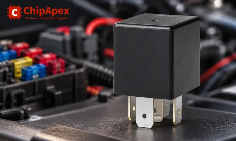
Learn the relay definition, coil and contact operation, NO and NC forms, load ratings and suppression choices. Compare mechanical, reed and solid-state types.
Read More
ADS7800KUE4 is listed in the Analog To Digital Converters (ADC) range at ChipApex. The manufacturer field lists Texas Instruments. Its product description is 12-BIT…
Read More
The activity of extra discounts on wholesale prices is in full swing…
Please fill in your contact information and we will send you the latest wholesale price list.




