 ChipApex | Global Electronic Components Supplier

SEARCH
Search Product
Search Post
— IC芯片 | 连接器 | 传感器 | 被动器件 —
Search productSearch post
— IC芯片 | 连接器 | 传感器 | 被动器件 —
Consult the customer manager about the wholesale price.
consultation hotline:86-132-6715-2157
email:[email protected]
Contact the product manager for consultation. One-stop consultation is available.
Do you want a lower wholesale price? Please send us your inquiry and we will reply immediately.
DG221BDY-T1 is listed in the Analog Switches, Multiplexers, Demultiplexers range at ChipApex. The manufacturer field lists Vishay Siliconix. Its product description is IC SWITCH SPST-NCX4 90OHM 16SOIC. Review the specifications below when checking this part for your BOM.
The DG221BDY-T1 is a monolithic quad single-pole, single-throw (SPST) CMOS analog switch manufactured by Vishay Siliconix. It features independent onboard latches and a common write (WR) pin, allowing memory mapping and simultaneous switching of all channels as a single data byte. The device operates with dual supplies ranging from ±4.5 V to ±15 V, supporting an analog signal range of ±15 V. Key electrical parameters include a maximum on-resistance of 90 Ω at full temperature, turn-on time of 550 ns, and turn-off time of 340 ns. It handles continuous currents up to 20 mA with a power dissipation of 600 mW in the SOIC-16 package.
Verify component authenticity through authorized distributors or official manufacturer channels. Confirm RoHS compliance status and lead-free suffixes against current datasheets. Check for end-of-life notices or obsolescence warnings before finalizing procurement plans.
Select this component when precise analog signal routing requires integrated digital control logic within a single package. Ensure supply voltages remain within the specified ±15 V limits to maintain optimal on-resistance and switching performance characteristics.
This part belongs to the DG221B family of quad SPST analog switches. It shares functional similarities with other devices in the series but is distinguished by its specific latch architecture and SOIC-16 surface-mount packaging configuration.
Direct substitutes may include DG221BDJ-E3 for DIP packages or DG221BDY-E3 for tape-and-reel SOIC variants. Verify pinout compatibility and latch functionality before implementation.
When WR is low, the input latches are transparent, allowing data to pass through. When WR goes high, the selected state is latched, maintaining the switch position until the next write cycle.
The device supports an analog signal range equal to the supply rails, typically up to ±15 V when powered by ±15 V supplies.
Explore related parts through Interface, Integrated Circuits (ICs), all product categories, ChipApex homepage.
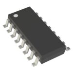 DG221BDY-T1

DG221BDY-T1 is listed in the Analog Switches, Multiplexers, Demultiplexers range at ChipApex. The manufacturer field lists Vishay Siliconix. Its product description is IC SWITCH…
Read More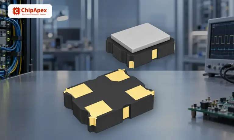
Understand how oscillators generate timing signals, how they differ from crystals, and which frequency, output and stability specs matter when choosing one.
Read More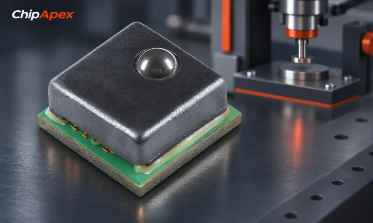
Understand load cell sensor output, bridge wiring and calibration. Learn how mV/V sensitivity, mechanics and ADC noise affect measurement accuracy.
Read More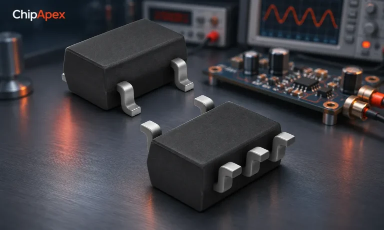
Learn how a JFET works and how to compare bias, leakage, noise and pinout. Review practical selection questions for high-impedance analog circuits.
Read More
DG221BDY-T1 is listed in the Analog Switches, Multiplexers, Demultiplexers range at ChipApex. The manufacturer field lists Vishay Siliconix. Its product description is IC SWITCH…
Read More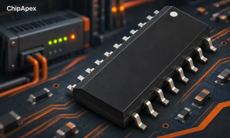
Learn what a shift register does, how bits move and when to use SIPO or PISO devices. Review latch timing, logic levels, output drive…
Read More
DG221BDY-T1 is listed in the Analog Switches, Multiplexers, Demultiplexers range at ChipApex. The manufacturer field lists Vishay Siliconix. Its product description is IC SWITCH…
Read More
DG221BDY-T1 is listed in the Analog Switches, Multiplexers, Demultiplexers range at ChipApex. The manufacturer field lists Vishay Siliconix. Its product description is IC SWITCH…
Read More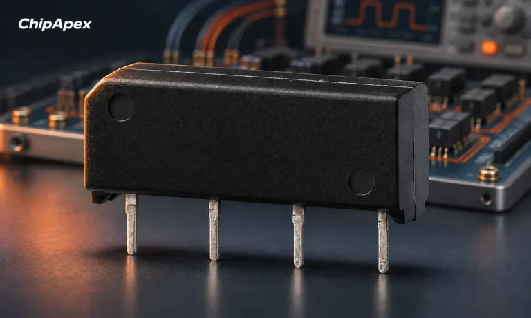
Choose a reed relay for signal switching. Understand hot and cold switching, leakage, contact resistance, isolation and measurement settling requirements.
Read More
DG221BDY-T1 is listed in the Analog Switches, Multiplexers, Demultiplexers range at ChipApex. The manufacturer field lists Vishay Siliconix. Its product description is IC SWITCH…
Read More
DG221BDY-T1 is listed in the Analog Switches, Multiplexers, Demultiplexers range at ChipApex. The manufacturer field lists Vishay Siliconix. Its product description is IC SWITCH…
Read More
DG221BDY-T1 is listed in the Analog Switches, Multiplexers, Demultiplexers range at ChipApex. The manufacturer field lists Vishay Siliconix. Its product description is IC SWITCH…
Read More
The activity of extra discounts on wholesale prices is in full swing…
Please fill in your contact information and we will send you the latest wholesale price list.





