 ChipApex | Global Electronic Components Supplier

SEARCH
Search Product
Search Post
— IC芯片 | 连接器 | 传感器 | 被动器件 —
Search productSearch post
— IC芯片 | 连接器 | 传感器 | 被动器件 —
Consult the customer manager about the wholesale price.
consultation hotline:86-132-6715-2157
email:[email protected]
Contact the product manager for consultation. One-stop consultation is available.
Do you want a lower wholesale price? Please send us your inquiry and we will reply immediately.
MC74HC4020ADTR2G is listed in the Counter Dividers range at ChipApex. The manufacturer field lists onsemi. Its product description is IC BINARY COUNTER 14BIT 16TSSOP. Review the specifications below when checking this part for your BOM.
The MC74HC4020ADTR2G is a high-performance silicon-gate CMOS 14-stage binary ripple counter manufactured by onsemi. It features 14 master-slave flip-flops with 12 stages brought out to pins, operating within a supply voltage range of 2.0 V to 6.0 V. The device supports a maximum clock frequency of 50 MHz at 6.0 V and includes an asynchronous active-high reset input. Packaged in a 16-lead TSSOP (DT suffix), it offers low input current and high noise immunity, compatible with standard CMOS outputs and LSTTL loads when pull-up resistors are used.
Verify the specific package suffix 'DT' corresponds to the 16-TSSOP configuration required for your PCB layout. Confirm that the ordering prefix matches the standard commercial grade, as prefixes like 'NLV' or suffixes '-Q' indicate automotive qualification and unique site control requirements. Ensure compatibility with the specified 2.0 V to 6.0 V operating range for your target application voltage.
Select this component when a 14-bit binary count is needed with direct access to intermediate stages. The HC series ensures compatibility with standard CMOS logic levels across a wide voltage range. Consider the internal ripple delay characteristics; if simultaneous output switching is critical, alternative synchronous counters may be more suitable than this ripple architecture.
This part belongs to the MC74HC4020A family of high-performance silicon-gate CMOS devices. It shares pinout compatibility with the standard CMOS MC14020B. The device is designed for general-purpose digital counting applications, offering robust performance with low power consumption and high noise immunity typical of modern CMOS technology.
MC74HC4020ADR2G
The reset input is asynchronous and active-high. Applying a high level to the Reset pin forces all Q outputs low immediately, regardless of the clock state.
State changes of the Q outputs do not occur simultaneously due to internal ripple delays between the cascaded flip-flops. This sequential switching can generate decoding spikes on the output lines.
Explore related parts through Logic, Integrated Circuits (ICs), all product categories, ChipApex homepage.
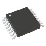 MC74HC4020ADTR2G
See how a MEMS gyroscope measures angular rate, why its angle estimate drifts, and which range, noise, interface and temperature specs to compare.
Read More
MC74HC4020ADTR2G is listed in the Counter Dividers range at ChipApex. The manufacturer field lists onsemi. Its product description is IC BINARY COUNTER 14BIT 16TSSOP.…
Read More
MC74HC4020ADTR2G is listed in the Counter Dividers range at ChipApex. The manufacturer field lists onsemi. Its product description is IC BINARY COUNTER 14BIT 16TSSOP.…
Read More
MC74HC4020ADTR2G is listed in the Counter Dividers range at ChipApex. The manufacturer field lists onsemi. Its product description is IC BINARY COUNTER 14BIT 16TSSOP.…
Read More
MC74HC4020ADTR2G is listed in the Counter Dividers range at ChipApex. The manufacturer field lists onsemi. Its product description is IC BINARY COUNTER 14BIT 16TSSOP.…
Read More
MC74HC4020ADTR2G is listed in the Counter Dividers range at ChipApex. The manufacturer field lists onsemi. Its product description is IC BINARY COUNTER 14BIT 16TSSOP.…
Read More
Understand thermal fuse operation, Tf, Th and Tm, electrical ratings and mounting. Check temperature limits and replacement requirements for your design.
Read More
Compare RC, crystal and MEMS oscillator circuits. Check ppm, jitter, load capacitance, startup margin and output compatibility before choosing a clock source.
Read More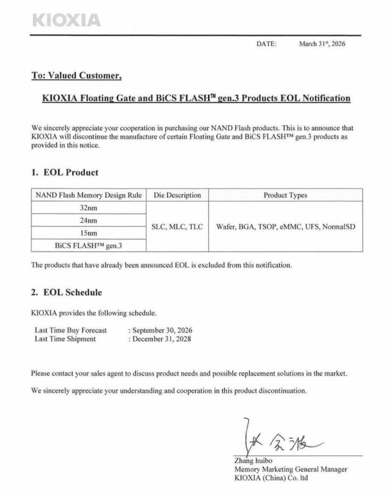
MC74HC4020ADTR2G is listed in the Counter Dividers range at ChipApex. The manufacturer field lists onsemi. Its product description is IC BINARY COUNTER 14BIT 16TSSOP.…
Read More
MC74HC4020ADTR2G is listed in the Counter Dividers range at ChipApex. The manufacturer field lists onsemi. Its product description is IC BINARY COUNTER 14BIT 16TSSOP.…
Read More
MC74HC4020ADTR2G is listed in the Counter Dividers range at ChipApex. The manufacturer field lists onsemi. Its product description is IC BINARY COUNTER 14BIT 16TSSOP.…
Read More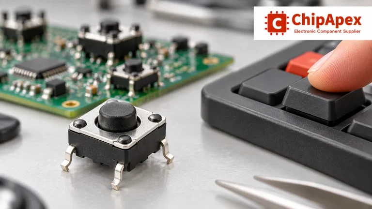
Choose tactile switches by operating force, travel, actuator height, footprint and lifetime. Check debounce, sealing and the assembled button mechanism.
Read More
The activity of extra discounts on wholesale prices is in full swing…
Please fill in your contact information and we will send you the latest wholesale price list.





