 ChipApex | Global Electronic Components Supplier

SEARCH
Search Product
Search Post
— IC芯片 | 连接器 | 传感器 | 被动器件 —
Search productSearch post
— IC芯片 | 连接器 | 传感器 | 被动器件 —
Consult the customer manager about the wholesale price.
consultation hotline:86-132-6715-2157
email:[email protected]
Contact the product manager for consultation. One-stop consultation is available.
Do you want a lower wholesale price? Please send us your inquiry and we will reply immediately.
SN74HC244DWRG4 is listed in the Buffers, Drivers, Receivers, Transceivers range at ChipApex. The manufacturer field lists Texas Instruments. Its product description is IC BUFFER NON-INVERT 6V 20SOIC. Review the specifications below when checking this part for your BOM.
The SN74HC244DWRG4 is an octal buffer and line driver featuring three-state outputs, manufactured by Texas Instruments. It operates within a supply voltage range of 2V to 6V. The device provides high-current outputs capable of driving up to 15 LSTTL loads. Key electrical parameters include a maximum static current (ICC) of 80µA at 6V and typical propagation delay (tpd) of 11ns. Output drive capability is specified as ±6mA at 5V with low input current of 1µA maximum.
Verify the specific package variant matches the required PCB footprint, as the DW suffix indicates SOIC-20. Confirm RoHS compliance status and lead finish details against the latest manufacturer documentation. Ensure the operating temperature range aligns with system requirements, noting potential variations between industrial and extended grades.
Select this component for applications requiring high-density bus buffering with wide voltage flexibility. The HC logic family offers balanced drive strength and low power consumption. Consider thermal resistance metrics if operating in enclosed environments. Verify that input transition times meet specifications to prevent excessive power dissipation or oscillation during operation.
This part belongs to the SNx4HC244 series of octal buffers and line drivers. It is designed to improve performance and density in 3-state memory address drivers and clock drivers. The device utilizes standard CMOS inputs and is available in multiple package options including SSOP, SOIC, PDIP, SOP, TSSOP, CDIP, and CFP.
SN74HC244DW
Each bank of four buffers has a separate output-enable (OE) input. When OE is low, data passes from A inputs to Y outputs. When OE is high, outputs enter a high-impedance state.
Unused inputs must be held at VCC or GND to ensure proper operation. Floating standard CMOS inputs can cause excessive power consumption and oscillation.
Explore related parts through Logic, Integrated Circuits (ICs), all product categories, ChipApex homepage.
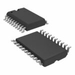 SN74HC244DWRG4
SN74HC244DWRG4 is listed in the Buffers, Drivers, Receivers, Transceivers range at ChipApex. The manufacturer field lists Texas Instruments. Its product description is IC BUFFER…
Read More
Learn how a JFET works and how to compare bias, leakage, noise and pinout. Review practical selection questions for high-impedance analog circuits.
Read More
SN74HC244DWRG4 is listed in the Buffers, Drivers, Receivers, Transceivers range at ChipApex. The manufacturer field lists Texas Instruments. Its product description is IC BUFFER…
Read More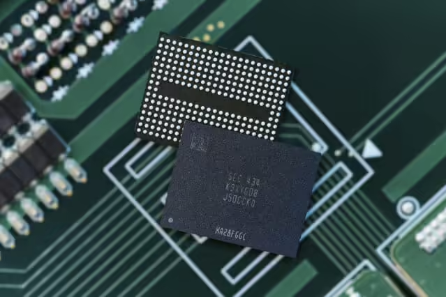
SN74HC244DWRG4 is listed in the Buffers, Drivers, Receivers, Transceivers range at ChipApex. The manufacturer field lists Texas Instruments. Its product description is IC BUFFER…
Read More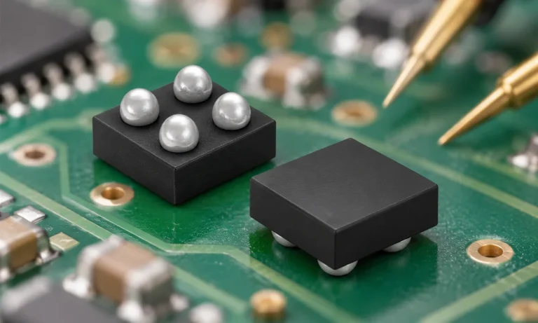
Understand how a comparator switches at a voltage threshold, why hysteresis prevents chatter, and which output and input specs matter.
Read More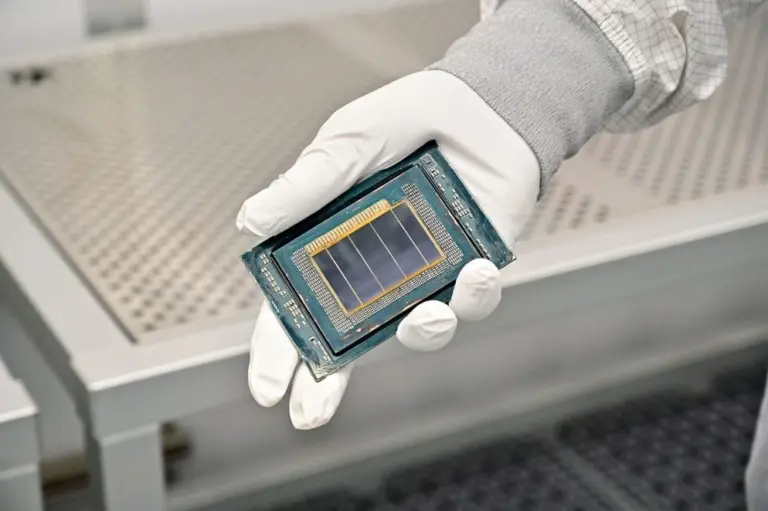
SN74HC244DWRG4 is listed in the Buffers, Drivers, Receivers, Transceivers range at ChipApex. The manufacturer field lists Texas Instruments. Its product description is IC BUFFER…
Read More
SN74HC244DWRG4 is listed in the Buffers, Drivers, Receivers, Transceivers range at ChipApex. The manufacturer field lists Texas Instruments. Its product description is IC BUFFER…
Read More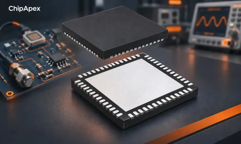
Learn how an analog front end conditions sensor signals. Compare gain, noise, filtering, ADC settling and integration options before selecting components.
Read More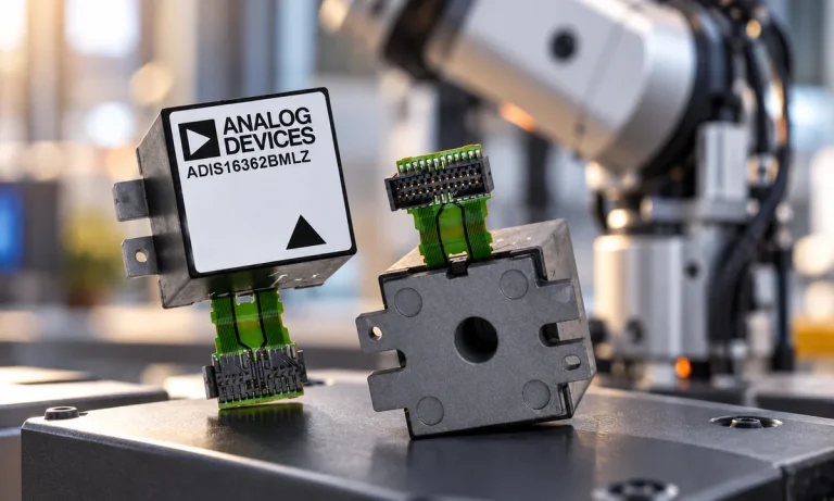
Learn what an IMU measures, how accelerometers and gyroscopes work together, why orientation estimates drift, and what to compare.
Read More
SN74HC244DWRG4 is listed in the Buffers, Drivers, Receivers, Transceivers range at ChipApex. The manufacturer field lists Texas Instruments. Its product description is IC BUFFER…
Read More
SN74HC244DWRG4 is listed in the Buffers, Drivers, Receivers, Transceivers range at ChipApex. The manufacturer field lists Texas Instruments. Its product description is IC BUFFER…
Read More
SN74HC244DWRG4 is listed in the Buffers, Drivers, Receivers, Transceivers range at ChipApex. The manufacturer field lists Texas Instruments. Its product description is IC BUFFER…
Read More
The activity of extra discounts on wholesale prices is in full swing…
Please fill in your contact information and we will send you the latest wholesale price list.





