ChipApex | Global Electronic Components Supplier

SEARCH
Search Product
Search Post
— IC芯片 | 连接器 | 传感器 | 被动器件 —
Search productSearch post
— IC芯片 | 连接器 | 传感器 | 被动器件 —
Consult the customer manager about the wholesale price.
consultation hotline:86-132-6715-2157
email:[email protected]
Contact the product manager for consultation. One-stop consultation is available.
Do you want a lower wholesale price? Please send us your inquiry and we will reply immediately.
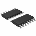
SN74HCS02DR is listed in the Inverter Gates range at ChipApex. The manufacturer field lists Texas Instruments. Its product description is IC GATE NOR 4CH 2-INP 14SOIC. Review the specifications below when checking this part for your BOM.
The SN74HCS02DR is a quadruple 2-input NOR gate with Schmitt-trigger inputs manufactured by Texas Instruments. It operates within a supply voltage range of 2V to 6V and supports an ambient temperature range from -40°C to +125°C. The device features balanced CMOS push-pull outputs capable of ±7.8mA drive current at 6V. Typical supply current is 0.1µA, with input leakage current specified at ±100nA. Propagation delay ranges from 6ns to 36ns depending on voltage.
Verify the specific package suffix 'D' corresponds to the SOIC-14 housing required for your PCB layout. Confirm that the operating environment remains within the specified -40°C to +125°C thermal limits. Ensure input signals do not exceed absolute maximum ratings to prevent clamp diode damage. Check for any recent documentation updates regarding threshold voltage revisions.
Select this component when noise immunity is critical due to its Schmitt-trigger architecture. It is suitable for low-power applications requiring wide voltage flexibility between 2V and 6V. Consider the SOIC-14 package dimensions during board design. Verify that output drive requirements stay within the ±7.8mA limit to avoid exceeding absolute maximum ratings.
This device belongs to the SN74HCS series, which combines high-speed CMOS performance with Schmitt-trigger functionality. It serves as a robust logic solution for environments with signal integrity challenges. The 'DR' designation indicates the specific surface-mount packaging variant offered by Texas Instruments for automated assembly processes.
SN74HCS02PW (TSSOP-14 package)
The Schmitt-trigger architecture allows the device to tolerate slow input transitions without causing excessive dynamic current consumption or undefined states.
Unused inputs must be terminated to either VCC or ground to prevent floating voltages; they should never be left disconnected.
Explore related parts through Logic, Integrated Circuits (ICs), all product categories, ChipApex homepage.
 SN74HCS02DR

SN74HCS02DR is listed in the Inverter Gates range at ChipApex. The manufacturer field lists Texas Instruments. Its product description is IC GATE NOR 4CH…
Read More
SN74HCS02DR is listed in the Inverter Gates range at ChipApex. The manufacturer field lists Texas Instruments. Its product description is IC GATE NOR 4CH…
Read More
SN74HCS02DR is listed in the Inverter Gates range at ChipApex. The manufacturer field lists Texas Instruments. Its product description is IC GATE NOR 4CH…
Read More
Choose an ADC converter by resolution, sample rate, noise and input design. Review practical tradeoffs and prepare component requirements for ChipApex.
Read More
SN74HCS02DR is listed in the Inverter Gates range at ChipApex. The manufacturer field lists Texas Instruments. Its product description is IC GATE NOR 4CH…
Read More
SN74HCS02DR is listed in the Inverter Gates range at ChipApex. The manufacturer field lists Texas Instruments. Its product description is IC GATE NOR 4CH…
Read More
SN74HCS02DR is listed in the Inverter Gates range at ChipApex. The manufacturer field lists Texas Instruments. Its product description is IC GATE NOR 4CH…
Read More
SN74HCS02DR is listed in the Inverter Gates range at ChipApex. The manufacturer field lists Texas Instruments. Its product description is IC GATE NOR 4CH…
Read More
SN74HCS02DR is listed in the Inverter Gates range at ChipApex. The manufacturer field lists Texas Instruments. Its product description is IC GATE NOR 4CH…
Read More
Compare variable capacitor types and varactor tuning. Understand capacitance-voltage curves, Q, bias and LC resonance before choosing a component.
Read More
Understand phototransistor operation, load-resistor selection, saturation and response time. Compare detector types and prepare component sourcing requirements.
Read More
Choose a vibration sensor for machine monitoring. Compare sensing methods, bandwidth, noise and mounting, then define the signal-chain requirements.
Read More
The activity of extra discounts on wholesale prices is in full swing…
Please fill in your contact information and we will send you the latest wholesale price list.