 ChipApex | Global Electronic Components Supplier

SEARCH
Search Product
Search Post
— IC芯片 | 连接器 | 传感器 | 被动器件 —
Search productSearch post
— IC芯片 | 连接器 | 传感器 | 被动器件 —
The trend of science and technology is changing rapidly.
A Zener diode is a diode designed to operate in reverse breakdown at a specified current. In a suitable circuit, it holds the voltage across itself within a limited range while the reverse current changes. Common uses include simple shunt regulation, voltage limiting and bias generation, with current limiting and power dissipation designed into the circuit.
The voltage printed in a product description is not an exact clamp at every current. Test current, tolerance, temperature and dynamic resistance all affect the actual operating voltage. Those conditions matter when a circuit needs a stable bias or a defined protection limit.
Below breakdown, a reverse-biased Zener passes a small leakage current. As voltage rises into the breakdown region, current increases steeply. A series resistor or another current-limiting element keeps the device within its operating limits.
The mechanisms commonly described as Zener tunneling and avalanche breakdown depend on junction construction and operating conditions. Parts sold as Zener diodes can use either mechanism or a combination. The practical selection task is to read the specified voltage-current and temperature behavior, rather than infer it from the product-family name.
Browse a zener diode by its required operating point, package and power conditions. Toshiba's diode explanation and Nexperia's AN90031 application note in the sources describe the reverse characteristic and the distinction between ideal and practical behavior.
In a basic positive shunt regulator, a resistor connects the supply to the output node. The Zener cathode connects to that node and its anode to the return. The load connects across the diode. This description identifies the functional connections; the actual part drawing establishes physical pin identity.
The resistor current is approximately (VIN − VZ)/R. That current divides between load current and Zener current, so IZ = IR − ILOAD. At low input voltage and high load, the diode may fall below the current needed for the intended regulation. At high input voltage and light load, it may dissipate too much power.
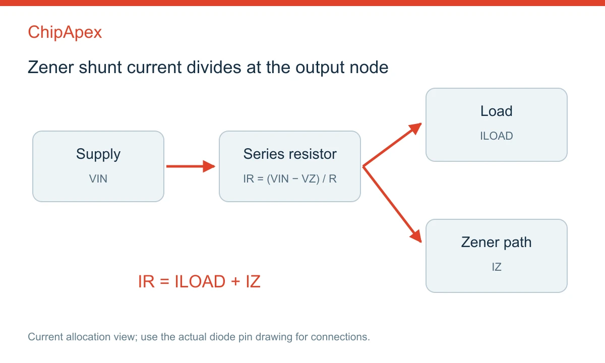
A Zener directly connected across a stiff voltage source without suitable current limiting can be damaged. The supply's current capability is part of the circuit, even when the nominal supply voltage looks close to the diode voltage.
Consider an illustrative 12 V supply with ±10% variation, a nominal 5.1 V Zener, a 470 Ω resistor and a load drawing up to 5 mA. Using nominal Zener voltage and resistor value gives these first estimates:
| Condition | Resistor current | Zener current | Approximate Zener power |
|---|---|---|---|
| 10.8 V input, 5 mA load | 12.1 mA | 7.1 mA | 36 mW |
| 13.2 V input, no load | 17.2 mA | 17.2 mA | 88 mW |
At the second point, resistor dissipation is approximately (13.2 − 5.1)²/470 = 0.14 W. These are assumed values for explaining the calculation. A final design must include resistor tolerance, the diode's voltage limits at the relevant currents, temperature and appropriate component derating.
The low-input/high-load point checks whether enough current remains for the required voltage behavior. The high-input/no-load point checks a likely high-dissipation condition. A load that switches between states can move the diode between those operating points. The device's pulse and thermal data determine whether other events are permissible.
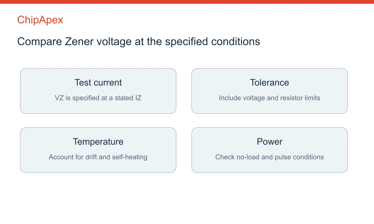
Rated Zener voltage is specified at a stated test current. If the circuit uses a different current, the voltage can differ from that number. Dynamic resistance describes the local change in voltage divided by the change in current. It is a local characteristic, not necessarily a constant over the full curve.
Leakage below breakdown matters when a node has high impedance or a battery budget is tight. A device suitable at several milliamps may behave differently when biased at only a few microamps. Check guaranteed limits and curves appropriate to that range.
Temperature changes the breakdown voltage and can also alter leakage. Self-heating links electrical current to junction temperature, so a room-temperature voltage measurement does not establish the operating value in an enclosure. Nexperia's application note covers these parameters and their measurement conditions; use the exact datasheet for final limits.
Where the circuit needs a tighter, lower-drift scale, compare a dedicated voltage reference against the required accuracy, noise and load. For a powered rail, an appropriate low dropout regulator circuit may provide a different solution. These components have distinct operating requirements and should not be treated as automatic drop-in replacements.
Both can use reverse-breakdown behavior, but their intended duties and ratings differ. A Zener is often selected for continuous bias or voltage stabilization. A TVS is commonly selected using transient pulse characteristics, including standoff, breakdown and clamping voltage at a stated pulse current.
The nominal breakdown voltage alone does not describe the voltage seen during a surge. The protection device, source impedance, pulse waveform and protected input limits need to be evaluated together. A low-power Zener should not be substituted for a pulse-rated protector merely because the voltage labels are similar.
For ordinary rectification or reverse-current blocking, a different diode type may be appropriate. Forward behavior, reverse rating, capacitance and recovery characteristics vary across diode families. Identify the required function before selecting by package or nominal voltage.
In a basic shunt circuit, the resistor limits current and absorbs the difference between supply and output voltage. Without suitable current limiting, breakdown current can exceed the diode's rating. Some circuits use another current-limiting arrangement instead, but the diode still needs to remain within its electrical and thermal limits.
No. The specified voltage has a tolerance and applies at a stated test current and temperature. Actual voltage also changes with current, dynamic resistance and heating. Use the guaranteed limits and relevant curves when deciding whether the circuit can meet a required bias or protection threshold.
Yes, it has a forward-conduction characteristic as well as its reverse-breakdown behavior. Forward operation is different from the usual Zener regulation function. Check the part's ratings and intended role; the ability to conduct forward does not make every Zener an appropriate replacement for a rectifier or switching diode.
A basic diode test may check a forward junction but often lacks the voltage or controlled current needed to characterize reverse breakdown. A suitable current-limited test arrangement is needed to assess voltage at the specified operating current. Also distinguish a quick fault check from verification across temperature and tolerance.
It can work for some small loads if the full current and power budget is acceptable. Increasing load current reduces the current left in the Zener; decreasing load increases diode dissipation. If the load range makes regulation or efficiency unsuitable, consider a regulator architecture matched to that requirement.
For ChipApex, include the required voltage tolerance, normal and fault currents, power or pulse conditions, temperature and package. For a replacement, provide the existing part number and circuit function. These details help distinguish a continuous-bias component from a transient-protection requirement.
Compare Pt100 and Pt1000 RTDs, two-, three- and four-wire connections, excitation and self-heating. Build an error budget from element to reported temperature.
View details
Compare RC, crystal and MEMS oscillator circuits. Check ppm, jitter, load capacitance, startup margin and output compatibility before choosing a clock source.
View details
Understand how oscillators generate timing signals, how they differ from crystals, and which frequency, output and stability specs matter when choosing one.
View details
Choose logic inverter ICs by thresholds, supply, output drive and delay. Compare standard and Schmitt-trigger inputs, power sequencing and replacement checks.
View details
The activity of extra discounts on wholesale prices is in full swing…
Please fill in your contact information and we will send you the latest wholesale price list.

