 ChipApex | Global Electronic Components Supplier

SEARCH
Search Product
Search Post
— IC芯片 | 连接器 | 传感器 | 被动器件 —
Search productSearch post
— IC芯片 | 连接器 | 传感器 | 被动器件 —
The trend of science and technology is changing rapidly.
The current divider formula gives the current in one branch of a parallel network. The voltage divider formula gives the voltage across part of a series network. Start by identifying which nodes are shared and where the output is measured. The same two resistors can give useful results in either arrangement, but their roles change.
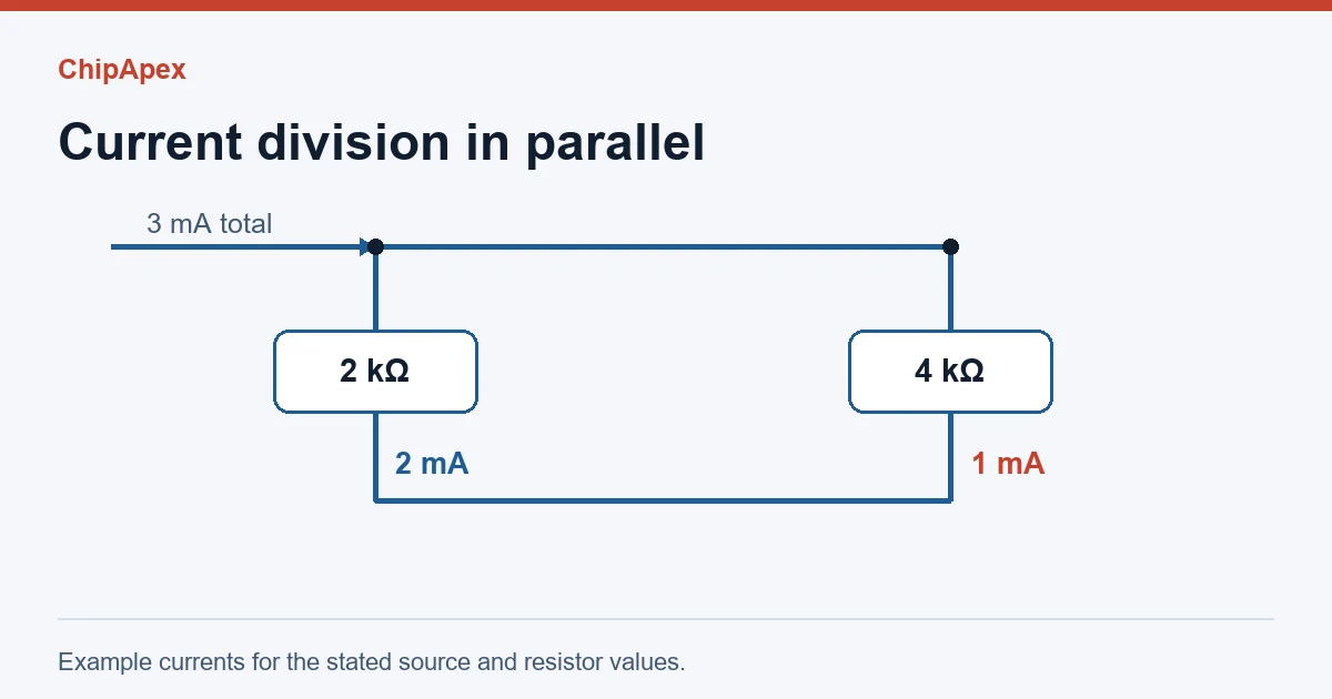
All parallel branches share the same voltage. If total current is known, each branch receives a share proportional to its conductance. For branch k, Iₖ = Iₜ × (1/Rₖ) ÷ Σ(1/R). With only two resistors, the expression for current in R₁ reduces to I₁ = Iₜ × R₂ ÷ (R₁ + R₂).
Consider a 3 mA source feeding 2 kΩ and 4 kΩ in parallel. The 2 kΩ branch takes 2 mA and the 4 kΩ branch takes 1 mA. Both have 4 V across them, and the branch currents add to the source current. Those two checks catch the common mistake of putting the wrong branch resistance in the numerator.
For three branches, keep the conductance form. With 2 kΩ, 4 kΩ and 4 kΩ fed by 4 mA, the conductance ratio is 2:1:1. The currents are 2 mA, 1 mA and 1 mA. MIT circuit notes on parallel resistors
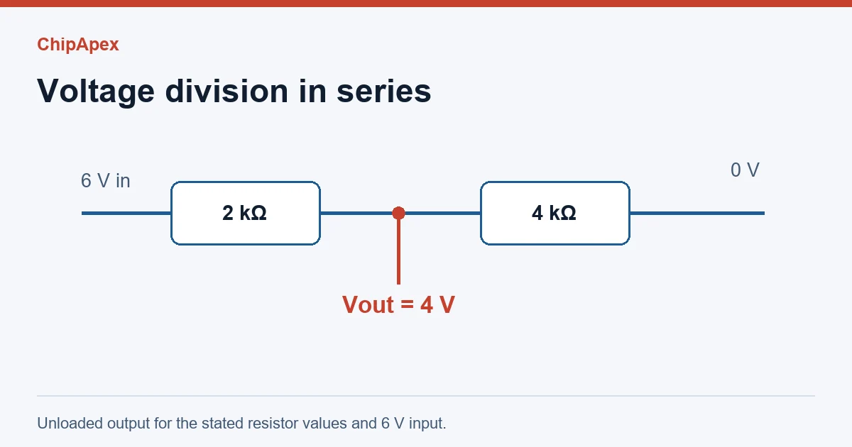
For a two-resistor divider, VOUT = VIN × Rbottom ÷ (Rtop + Rbottom), measured from the junction to the common return. The result assumes the output draws negligible current. With 6 V applied to the same 2 kΩ and 4 kΩ resistors in series, the current is 1 mA. The 4 kΩ bottom resistor drops 4 V and the top drops 2 V.
With three series resistors, add all three in the denominator. The numerator contains only the resistors between the measured node and the reference node. A potentiometer works on the same principle when the wiper is lightly loaded. Its electrical taper determines how voltage changes with shaft position.
| Rule | What is equal? | Quick check |
|---|---|---|
| Series voltage divider | Current through each series resistor | Individual drops sum to the supply voltage |
| Parallel current divider | Voltage across every branch | Branch currents sum to the input current |
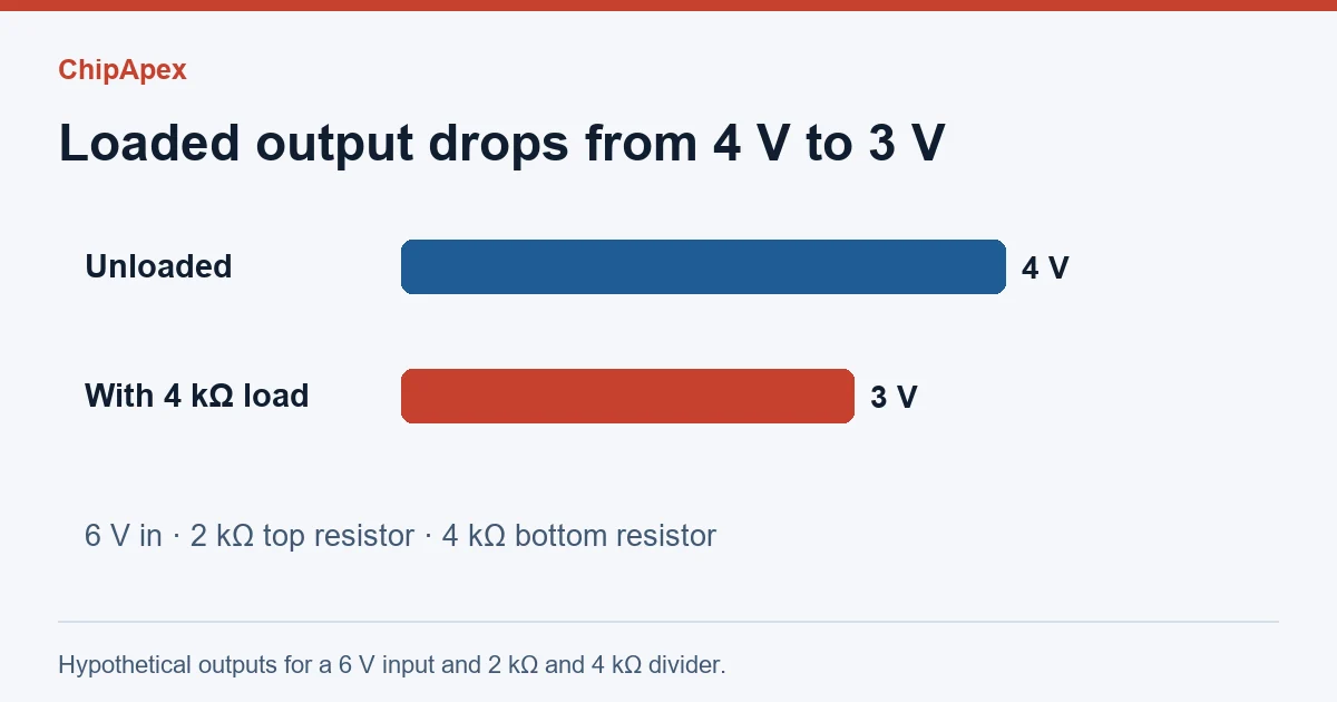
A 4 kΩ load across the 4 kΩ bottom resistor makes their parallel equivalent 2 kΩ. The circuit now has 2 kΩ above and 2 kΩ below the measured node, so the 6 V source gives 3 V at the output. The unloaded prediction of 4 V is 1 V too high. This is why a divider that reads correctly with the load disconnected can read low after it is connected.
Another way to calculate the same result is to treat the unloaded output as a 4 V source in series with the divider’s Thévenin resistance, 2 kΩ ∥ 4 kΩ = 1.33 kΩ. With a 4 kΩ load, 4 V × 4 ÷ (4 + 1.33) is approximately 3 V. This approach is handy when you want to compare several loads without redrawing the circuit each time. TI circuit equations note
For a sensor input, check steady-state input impedance and leakage first. If an ADC samples through a switch and capacitor, also check its acquisition time and permitted source resistance. Lower divider resistances reduce loading error but draw more current. The ChipApex electronics engineering calculators can support related circuit checks.
The conductance of the target branch starts as 1/R₁. Multiplying the numerator and denominator by R₁R₂ leaves R₂ above the line. The lower-resistance branch still receives more current.
When the load impedance is high enough that its effect is smaller than the design’s error budget. Calculate the loaded value when accuracy matters.
Use the top resistance in the numerator and observe the meter polarity. With 6 V, 2 kΩ at the top and 4 kΩ at the bottom, its drop is 2 V.
For linear steady-state AC, substitute complex impedances and use phasors at the frequency of interest. The resulting ratios can affect phase as well as magnitude.
Its output moves as load changes. For a load that needs a stable supply, characterize its demand and consider a regulated rail.
Discover what DRAM is, how it works, its types, and why choosing authentic, RoHS-compliant DRAM chips matters. Source reliable DRAM from ChipApex—global supplier with full traceability.
View details
Compare variable capacitor types and varactor tuning. Understand capacitance-voltage curves, Q, bias and LC resonance before choosing a component.
View details
Choose a limit switch by actuator, travel, contact ratings and environment. Understand pretravel, overtravel and practical checks for machine integration.
View details
Navigate the MPU landscape (NXP, TI, ST) with our guide. Discover ARM Cortex-A architecture, hidden costs of MPUs, longevity risks, and source authentic industrial-grade MPUs with full BOM support at ChipApex.
View details
The activity of extra discounts on wholesale prices is in full swing…
Please fill in your contact information and we will send you the latest wholesale price list.