 ChipApex | Global Electronic Components Supplier

SEARCH
Search Product
Search Post
— IC芯片 | 连接器 | 传感器 | 被动器件 —
Search productSearch post
— IC芯片 | 连接器 | 传感器 | 被动器件 —
The trend of science and technology is changing rapidly.
A neutral earthing resistor (NER) connects the neutral of a transformer or generator to earth through a defined resistance. It limits current during a line-to-earth fault so the protection system can detect and respond to the fault within its design limits. North American documentation often calls the same device a neutral grounding resistor (NGR).
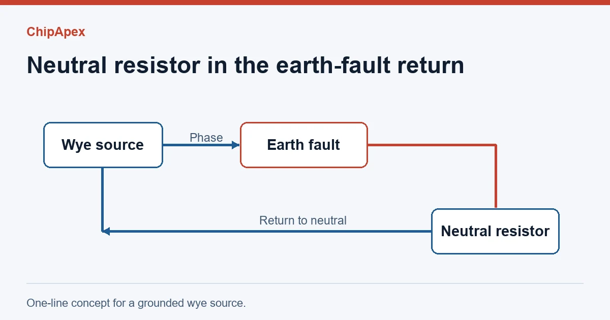
On a grounded wye secondary, the resistor provides a return path between earth and the source neutral. During a single line-to-earth fault, current flows out through the affected phase, through the fault and the grounding network, and back to the source through the resistor. The resistor belongs in the neutral grounding branch. The equipment protective-earth network still bonds exposed conductive parts according to the system design.
A delta source has no natural neutral terminal. Some installations use a grounding transformer to establish one. The transformer and resistor then have to be specified together. Confirm which winding voltage the resistor sees and where the sensing CT is located before comparing equipment. Telema’s neutral grounding resistor documentation provides a manufacturer perspective on the application.
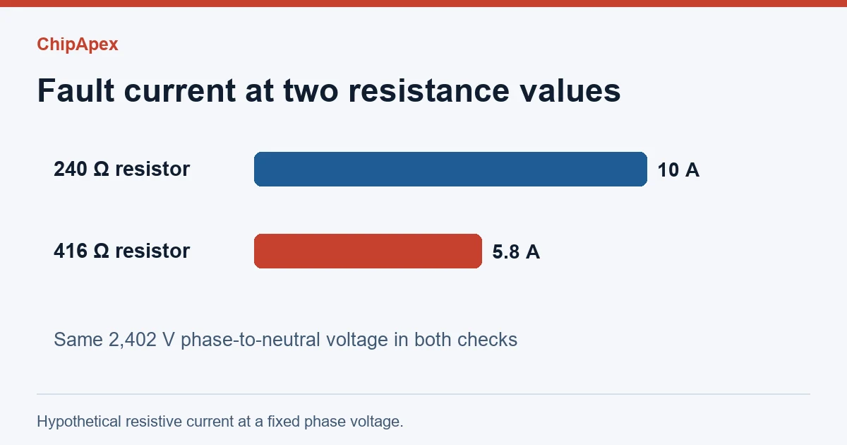
For a first-pass estimate on a wye system, use the phase-to-neutral voltage. If the resistor dominates the fault-loop impedance, divide that voltage by the target resistive fault current. This gives the current in the resistive path. Actual fault current also depends on source and grounding impedances, system capacitance and fault conditions.
Suppose a 4.16 kV line-to-line system is designed for about 10 A through the grounding resistor. The phase-to-neutral voltage is approximately 4,160 ÷ √3 = 2,402 V, and the first-pass resistance is 2,402 ÷ 10 ≈ 240 Ω. The resistor would dissipate roughly 24 kW at that current during the fault. Using 4,160 V in the same calculation would give 416 Ω and only about 5.8 A through the resistor at 2,402 V. Both calculations are hypothetical. An installation needs a fault study and a coordinated protection design.
Specify rated voltage, current, resistance tolerance and fault duration together. A time rating describes the duty the assembly is designed to withstand. For example, a short-time rating must be compatible with the longest clearing time assumed in the design, including any relevant backup protection.
| Input | What to document |
|---|---|
| Source configuration | Transformer or generator winding, system voltage and neutral availability |
| Ground-fault design | Target resistive current, charging-current assessment and relay pickup |
| Thermal duty | Rated current, duration or continuous duty, and the applicable ambient conditions |
| Physical integration | Enclosure, insulation level, entry points, CT placement and monitoring requirements |
Check whether the scheme detects a disconnected resistor. An open neutral-to-earth path can defeat the intended grounding behavior. A resistor monitor may supervise continuity separately from the relay function that detects a ground fault. Review the sensing and trip logic against the approved protection drawings. Littelfuse protection relays and controls catalog
The transformers catalog provides context for the source side of the design. If you’re requesting sourcing help, send the one-line diagram, required grounding duty and original part number if available.
They commonly refer to a neutral-to-earth resistor used to limit ground-fault current. Check how the project specification defines the complete assembly, especially if it includes a CT or monitor.
Voltage gives only one input. The system study sets fault-current requirements, and the protection design determines the duration and detection thresholds the assembly must support.
Joule heating accumulates while current flows. A resistor designed to withstand a specified current for seconds may reach excessive temperature if that current continues.
The intended resistive path disappears. The network can behave more like an ungrounded system until the fault is addressed. Verify how the approved scheme monitors that path.
The resistor limits fault current. Relays and interrupting devices carry out detection and clearing according to the protection design.
Select a DC-DC converter by input range, topology, isolation and temperature. Compare ripple, efficiency and load limits before choosing a component.
View details
Learn how a TRIAC switches AC loads. Understand triggering, latching, holding current, phase control and thermal limits before choosing a component.
View details
Learn how logic gates work, read AND, NAND and XOR truth tables, and choose a gate IC by input thresholds, output levels, propagation delay and package.
View details
Learn how a JFET works and how to compare bias, leakage, noise and pinout. Review practical selection questions for high-impedance analog circuits.
View details
The activity of extra discounts on wholesale prices is in full swing…
Please fill in your contact information and we will send you the latest wholesale price list.