 ChipApex | Global Electronic Components Supplier

SEARCH
Search Product
Search Post
— IC芯片 | 连接器 | 传感器 | 被动器件 —
Search productSearch post
— IC芯片 | 连接器 | 传感器 | 被动器件 —
Consult the customer manager about the wholesale price.
consultation hotline:86-132-6715-2157
email:[email protected]
Contact the product manager for consultation. One-stop consultation is available.
Do you want a lower wholesale price? Please send us your inquiry and we will reply immediately.
25AA040AT-I/SN is listed in the Memory IC range at ChipApex. The manufacturer field lists Microchip Technology. Its product description is IC EEPROM 4KBIT SPI 10MHZ 8SOIC. Review the specifications below when checking this part for your BOM.
The Microchip Technology 25AA040AT-I/SN is a 4 Kbit (512 x 8) Serial Electrically Erasable Programmable Read-Only Memory (EEPROM). It operates via a SPI-compatible serial bus with a maximum clock frequency of 10 MHz. The device supports a supply voltage range of 1.8 V to 5.5 V and functions within an industrial temperature range of -40°C to +85°C. It features self-timed erase and write cycles, block write protection, and data retention exceeding 200 years.
Verify the specific suffix 'I' confirms the Industrial temperature grade (-40°C to +85°C) and 'SN' denotes the SOIC-8 package. Confirm the 'T' indicates tape-and-reel packaging. Ensure the datasheet DS21827H matches the required electrical characteristics for your operating voltage.
Select this component when low-voltage operation down to 1.8 V is required alongside standard SPI compatibility. It is suitable for applications needing high endurance and long-term data retention. Compare against the 25LC040A if a higher minimum voltage of 2.5 V is acceptable for cost or availability reasons.
This part belongs to the 25XX040A family of 4 Kbit SPI EEPROMs from Microchip Technology. The family includes variants like the 25LC040A which differ primarily in their minimum operating voltage requirements. These devices are designed for non-volatile data storage in embedded systems requiring reliable byte-level access.
The 25LC040AT-I/SN is a direct functional substitute within the same package, though it requires a minimum supply voltage of 2.5 V instead of 1.8 V. Verify voltage headroom in the target design before substitution.
The HOLD pin allows the user to pause transmission to the device mid-sequence without resetting the serial pointer. Transitions on SI, SCK, and SO are ignored while held low, and communication resumes when the pin is brought high.
Writes are inhibited by default upon power-up. A WREN instruction must be issued to set the write enable latch. Additionally, the WP pin can force all writes to be disabled regardless of the latch state.
Explore related parts through Memory, Integrated Circuits (ICs), all product categories, ChipApex homepage.
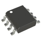 25AA040AT-I/SN

25AA040AT-I/SN is listed in the Memory IC range at ChipApex. The manufacturer field lists Microchip Technology. Its product description is IC EEPROM 4KBIT SPI…
Read More
25AA040AT-I/SN is listed in the Memory IC range at ChipApex. The manufacturer field lists Microchip Technology. Its product description is IC EEPROM 4KBIT SPI…
Read More
25AA040AT-I/SN is listed in the Memory IC range at ChipApex. The manufacturer field lists Microchip Technology. Its product description is IC EEPROM 4KBIT SPI…
Read More
25AA040AT-I/SN is listed in the Memory IC range at ChipApex. The manufacturer field lists Microchip Technology. Its product description is IC EEPROM 4KBIT SPI…
Read More
25AA040AT-I/SN is listed in the Memory IC range at ChipApex. The manufacturer field lists Microchip Technology. Its product description is IC EEPROM 4KBIT SPI…
Read More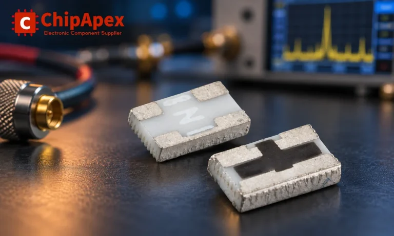
Understand RF attenuator dB values, fixed and programmable types, impedance, power limits and noise tradeoffs before choosing parts for an RF signal path.
Read More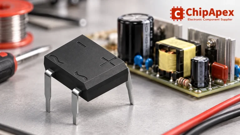
Select a bridge rectifier by reverse voltage, capacitor charging current, startup surge and cooling. Work through a stated DC voltage and ripple example.
Read More
25AA040AT-I/SN is listed in the Memory IC range at ChipApex. The manufacturer field lists Microchip Technology. Its product description is IC EEPROM 4KBIT SPI…
Read More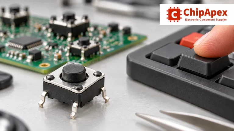
Understand tactile switches, PCB and keyboard differences, four-pin wiring, debounce, force, travel and replacement checks for reliable control inputs.
Read More
25AA040AT-I/SN is listed in the Memory IC range at ChipApex. The manufacturer field lists Microchip Technology. Its product description is IC EEPROM 4KBIT SPI…
Read More
25AA040AT-I/SN is listed in the Memory IC range at ChipApex. The manufacturer field lists Microchip Technology. Its product description is IC EEPROM 4KBIT SPI…
Read More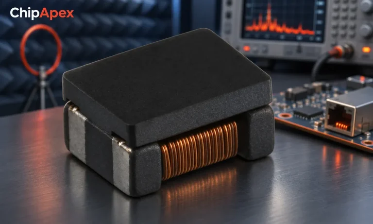
Select a common mode choke using noise frequency, current, insulation and signal integrity. Understand impedance curves, layout and filter limitations.
Read More
The activity of extra discounts on wholesale prices is in full swing…
Please fill in your contact information and we will send you the latest wholesale price list.





