 ChipApex | Global Electronic Components Supplier

SEARCH
Search Product
Search Post
— IC芯片 | 连接器 | 传感器 | 被动器件 —
Search productSearch post
— IC芯片 | 连接器 | 传感器 | 被动器件 —
Consult the customer manager about the wholesale price.
consultation hotline:86-132-6715-2157
email:[email protected]
Contact the product manager for consultation. One-stop consultation is available.
Do you want a lower wholesale price? Please send us your inquiry and we will reply immediately.
25AA160CT-I/MS is listed in the Memory IC range at ChipApex. The manufacturer field lists Microchip Technology. Its product description is IC EEPROM 16KBIT SPI 10MHZ 8MSOP. Review the specifications below when checking this part for your BOM.
The Microchip Technology 25AA160CT-I/MS is a 16 Kbit (2048 x 8-bit) Serial Electrically Erasable PROM. It utilizes an SPI-compatible serial bus for communication, supporting clock frequencies up to 10 MHz. The device operates within a supply voltage range of 1.8V to 5.5V and features a 16-byte page size. It is housed in an 8-lead MSOP package and supports industrial temperature ranges from -40°C to +85°C.
Verify the specific suffix 'T' indicates tape and reel packaging when ordering. Confirm the 'I' designation matches the required industrial temperature range of -40°C to +85°C. Ensure the 'C' variant with 16-byte page size aligns with application buffer requirements rather than the 'D' variant's 32-byte page. Cross-reference the MSOP package dimensions against PCB layout constraints.
Select this component for applications requiring low-voltage operation down to 1.8V. Choose the 'C' version specifically if the application logic relies on 16-byte page boundaries. Consider the MSOP package for space-constrained surface-mount designs. Verify that the host microcontroller supports the required SPI mode and timing parameters for reliable data transfer at the target clock speed.
This part belongs to the 25XX160C/D family of 16 Kbit Serial EEPROMs. The 'AA' prefix denotes 1.8V to 5.5V operation, distinguishing it from the 'LC' series which requires 2.5V minimum. The 'C' suffix specifies a 16-byte page size, whereas 'D' variants offer 32-byte pages. This family shares common instruction sets and functional descriptions across different package options.
25AA160AT-I/MS
The HOLD pin allows the user to pause serial communication without resetting the sequence. When pulled low while SCK is low, the SI, SCK, and SO pins enter a high-impedance state. Communication resumes when HOLD is brought high while SCK is low.
The internal write cycle time is a maximum of 5 ms. During this period, the device ignores access attempts to the memory array.
The write enable latch must be set using the WREN instruction before any write operation. It is automatically reset after power-up, upon successful execution of WRDI, WRSR, or WRITE instructions.
Explore related parts through Memory, Integrated Circuits (ICs), all product categories, ChipApex homepage.
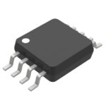 25AA160CT-I/MS

25AA160CT-I/MS is listed in the Memory IC range at ChipApex. The manufacturer field lists Microchip Technology. Its product description is IC EEPROM 16KBIT SPI…
Read More
25AA160CT-I/MS is listed in the Memory IC range at ChipApex. The manufacturer field lists Microchip Technology. Its product description is IC EEPROM 16KBIT SPI…
Read More
Understand UART protocol framing, baud rate and electrical interfaces. Learn 8N1 timing, TX/RX wiring, buffering and practical troubleshooting steps.
Read More
Understand thermal fuse operation, Tf, Th and Tm, electrical ratings and mounting. Check temperature limits and replacement requirements for your design.
Read More
25AA160CT-I/MS is listed in the Memory IC range at ChipApex. The manufacturer field lists Microchip Technology. Its product description is IC EEPROM 16KBIT SPI…
Read More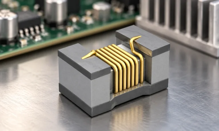
See when an inductor behaves linearly, how DC bias and saturation reduce inductance, and which current and temperature curves to check.
Read More
Compare RC, crystal and MEMS oscillator circuits. Check ppm, jitter, load capacitance, startup margin and output compatibility before choosing a clock source.
Read More
25AA160CT-I/MS is listed in the Memory IC range at ChipApex. The manufacturer field lists Microchip Technology. Its product description is IC EEPROM 16KBIT SPI…
Read More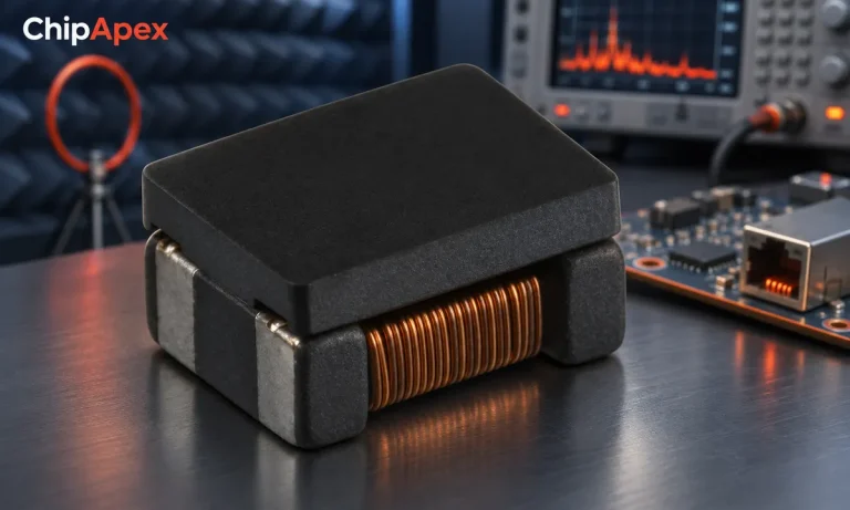
Select a common mode choke using noise frequency, current, insulation and signal integrity. Understand impedance curves, layout and filter limitations.
Read More
Learn how a JFET works and how to compare bias, leakage, noise and pinout. Review practical selection questions for high-impedance analog circuits.
Read More
25AA160CT-I/MS is listed in the Memory IC range at ChipApex. The manufacturer field lists Microchip Technology. Its product description is IC EEPROM 16KBIT SPI…
Read More
25AA160CT-I/MS is listed in the Memory IC range at ChipApex. The manufacturer field lists Microchip Technology. Its product description is IC EEPROM 16KBIT SPI…
Read More
The activity of extra discounts on wholesale prices is in full swing…
Please fill in your contact information and we will send you the latest wholesale price list.





