 ChipApex | Global Electronic Components Supplier

SEARCH
Search Product
Search Post
— IC芯片 | 连接器 | 传感器 | 被动器件 —
Search productSearch post
— IC芯片 | 连接器 | 传感器 | 被动器件 —
Consult the customer manager about the wholesale price.
consultation hotline:86-132-6715-2157
email:[email protected]
Contact the product manager for consultation. One-stop consultation is available.
Do you want a lower wholesale price? Please send us your inquiry and we will reply immediately.
74ACT8541QWRKSRQ1 is listed in the Buffers, Drivers, Receivers, Transceivers range at ChipApex. The manufacturer field lists Texas Instruments. Its product description is AUTOMOTIVE EIGHT-CHANNEL 4.5V-TO. Review the specifications below when checking this part for your BOM.
The SN74ACT8541-Q1 is an automotive-grade octal buffer with 3-state outputs and Schmitt-trigger inputs. It operates within a supply voltage range of 4.5V to 5.5V. The device provides continuous output drive currents of ±24mA at 5V, supporting up to ±75mA in short bursts. Propagation delays are specified at a maximum of 9.6ns under standard load conditions. It supports operation across a temperature range from -40°C to +125°C.
Verify the specific package suffix (RKS, PW, or DGS) matches the required footprint, as electrical performance remains consistent across packages. Confirm AEC-Q100 qualification requirements align with target automotive standards. Ensure design accounts for thermal dissipation limits defined in absolute maximum ratings during high-current operation.
Select this component when interfacing with TTL logic levels requiring noise immunity via Schmitt triggers. Suitable for applications needing simultaneous control of eight channels with independent enable inputs. Consider the wettable flank feature in the RKS package for improved automatic optical inspection reliability compared to standard QFN variants.
This device belongs to the SN74ACT series of logic buffers. It shares functional similarities with other octal buffers but distinguishes itself through integrated Schmitt-trigger inputs and automotive qualification. The ACT series typically offers higher speed and drive capability compared to standard AC logic families.
SN74ACT8541PWQ1
Both OE1 and OE2 must be low for the outputs to be active. If either pin is high, all outputs enter the high-impedance state.
Unused inputs must never be left floating. They should be terminated to VCC or GND, preferably using a pull-up or pull-down resistor such as 10kΩ.
Explore related parts through Logic, Integrated Circuits (ICs), all product categories, ChipApex homepage.
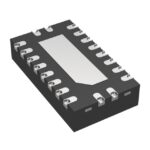 74ACT8541QWRKSRQ1
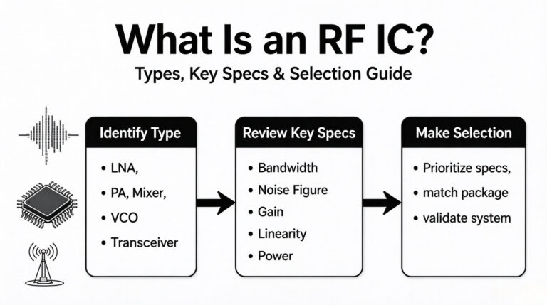
74ACT8541QWRKSRQ1 is listed in the Buffers, Drivers, Receivers, Transceivers range at ChipApex. The manufacturer field lists Texas Instruments. Its product description is AUTOMOTIVE EIGHT-CHANNEL…
Read More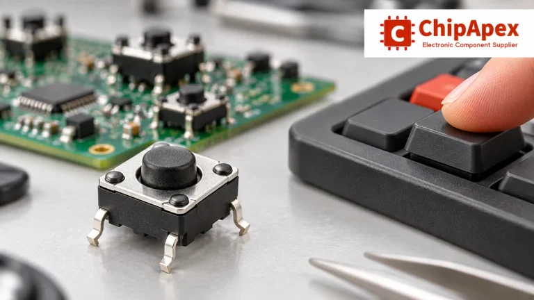
Choose tactile switches by operating force, travel, actuator height, footprint and lifetime. Check debounce, sealing and the assembled button mechanism.
Read More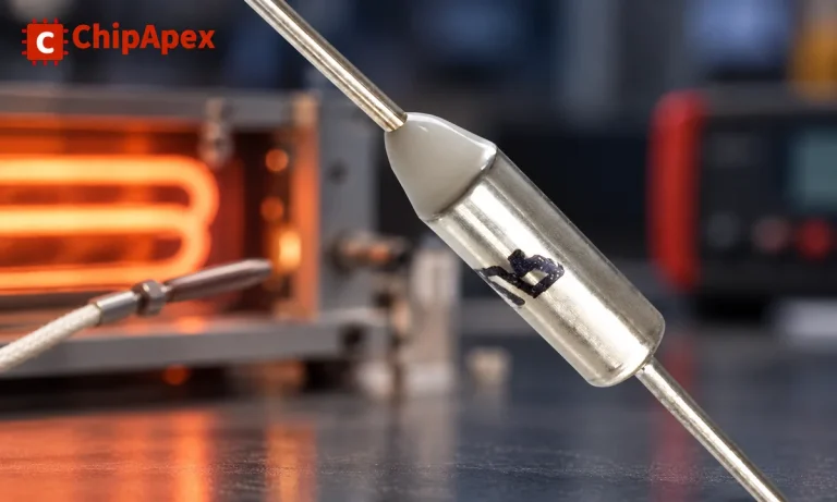
Understand thermal fuse operation, Tf, Th and Tm, electrical ratings and mounting. Check temperature limits and replacement requirements for your design.
Read More
74ACT8541QWRKSRQ1 is listed in the Buffers, Drivers, Receivers, Transceivers range at ChipApex. The manufacturer field lists Texas Instruments. Its product description is AUTOMOTIVE EIGHT-CHANNEL…
Read More
74ACT8541QWRKSRQ1 is listed in the Buffers, Drivers, Receivers, Transceivers range at ChipApex. The manufacturer field lists Texas Instruments. Its product description is AUTOMOTIVE EIGHT-CHANNEL…
Read More
74ACT8541QWRKSRQ1 is listed in the Buffers, Drivers, Receivers, Transceivers range at ChipApex. The manufacturer field lists Texas Instruments. Its product description is AUTOMOTIVE EIGHT-CHANNEL…
Read More
74ACT8541QWRKSRQ1 is listed in the Buffers, Drivers, Receivers, Transceivers range at ChipApex. The manufacturer field lists Texas Instruments. Its product description is AUTOMOTIVE EIGHT-CHANNEL…
Read More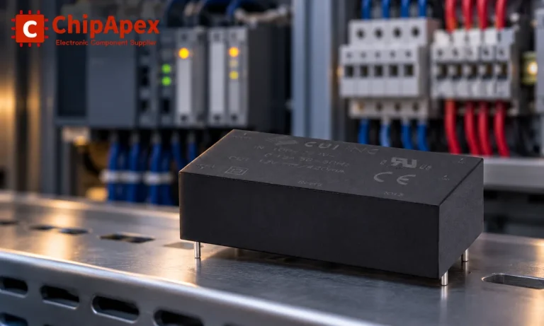
Choose an AC to DC converter by input range, output demand, isolation, efficiency and thermal derating. Compare architectures and check installation needs.
Read More
74ACT8541QWRKSRQ1 is listed in the Buffers, Drivers, Receivers, Transceivers range at ChipApex. The manufacturer field lists Texas Instruments. Its product description is AUTOMOTIVE EIGHT-CHANNEL…
Read More
74ACT8541QWRKSRQ1 is listed in the Buffers, Drivers, Receivers, Transceivers range at ChipApex. The manufacturer field lists Texas Instruments. Its product description is AUTOMOTIVE EIGHT-CHANNEL…
Read More
74ACT8541QWRKSRQ1 is listed in the Buffers, Drivers, Receivers, Transceivers range at ChipApex. The manufacturer field lists Texas Instruments. Its product description is AUTOMOTIVE EIGHT-CHANNEL…
Read More
74ACT8541QWRKSRQ1 is listed in the Buffers, Drivers, Receivers, Transceivers range at ChipApex. The manufacturer field lists Texas Instruments. Its product description is AUTOMOTIVE EIGHT-CHANNEL…
Read More
The activity of extra discounts on wholesale prices is in full swing…
Please fill in your contact information and we will send you the latest wholesale price list.





