 ChipApex | Global Electronic Components Supplier

SEARCH
Search Product
Search Post
— IC芯片 | 连接器 | 传感器 | 被动器件 —
Search productSearch post
— IC芯片 | 连接器 | 传感器 | 被动器件 —
Consult the customer manager about the wholesale price.
consultation hotline:86-132-6715-2157
email:[email protected]
Contact the product manager for consultation. One-stop consultation is available.
Do you want a lower wholesale price? Please send us your inquiry and we will reply immediately.
74LVT14D,112 is listed in the Inverter Gates range at ChipApex. The manufacturer field lists Nexperia USA Inc.. Its product description is IC INVERT SCHMITT 6CH 1-INP 14SO. Review the specifications below when checking this part for your BOM.
The Nexperia 74LVT14D,112 is a hex inverter with Schmitt-trigger inputs housed in a 14-lead SO plastic small outline package (SOT108-1). It operates within a supply voltage range of 2.7 V to 3.6 V and features overvoltage tolerant inputs up to 5.5 V. The device provides an output capability of +32 mA/-20 mA and includes IOFF circuitry for partial power-down applications. It complies with JEDEC standard JESD8C and supports operation from -40 °C to +85 °C.
Verify the specific ordering suffix '112' corresponds to the tube packaging format required for your assembly line. Confirm that the SO14 package variant matches your PCB footprint specifications. Ensure design compliance with the specified operating temperature range and absolute maximum ratings to maintain device reliability.
Select this component when designing circuits requiring noise immunity against slow signal transitions or where direct interfacing with TTL logic levels is necessary. The inclusion of bus hold inputs simplifies board layout by removing the requirement for external pull-up components on unconnected pins.
This part belongs to the 74LVT series of low-voltage CMOS logic devices manufactured by Nexperia. It is specifically designed for 3.3 V applications while maintaining compatibility with legacy 5 V systems through its overvoltage tolerant inputs and TTL-compatible thresholds.
Public confirmed substitute part numbers include 74LVT14PW,118 and 74LVT14BQ,118.
Bus hold data inputs eliminate the need for external pull-up resistors to define unused inputs.
The IOFF circuitry disables the output to prevent potentially damaging backflow current through the device when it is powered down.
Explore related parts through Logic, Integrated Circuits (ICs), all product categories, ChipApex homepage.
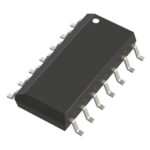 74LVT14D,112
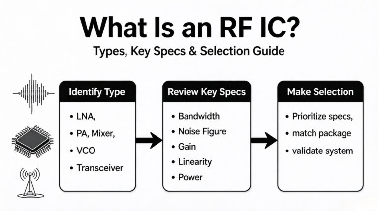
74LVT14D,112 is listed in the Inverter Gates range at ChipApex. The manufacturer field lists Nexperia USA Inc.. Its product description is IC INVERT SCHMITT…
Read More74LVT14D,112 is listed in the Inverter Gates range at ChipApex. The manufacturer field lists Nexperia USA Inc.. Its product description is IC INVERT SCHMITT…
Read More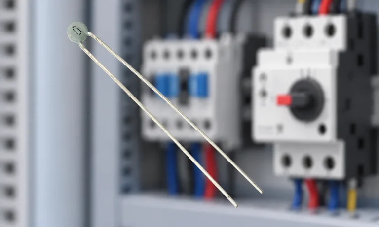
Learn why PTC resistance rises with temperature, how it differs from NTC, and which ratings matter for sensing and protection.
Read More
74LVT14D,112 is listed in the Inverter Gates range at ChipApex. The manufacturer field lists Nexperia USA Inc.. Its product description is IC INVERT SCHMITT…
Read More
74LVT14D,112 is listed in the Inverter Gates range at ChipApex. The manufacturer field lists Nexperia USA Inc.. Its product description is IC INVERT SCHMITT…
Read More
74LVT14D,112 is listed in the Inverter Gates range at ChipApex. The manufacturer field lists Nexperia USA Inc.. Its product description is IC INVERT SCHMITT…
Read More
74LVT14D,112 is listed in the Inverter Gates range at ChipApex. The manufacturer field lists Nexperia USA Inc.. Its product description is IC INVERT SCHMITT…
Read More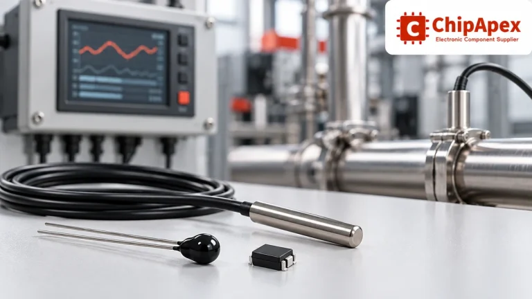
Compare thermistors, RTDs, thermocouples and temperature ICs. Learn how range, accuracy, response, interfaces and mounting affect component selection.
Read More
74LVT14D,112 is listed in the Inverter Gates range at ChipApex. The manufacturer field lists Nexperia USA Inc.. Its product description is IC INVERT SCHMITT…
Read More
74LVT14D,112 is listed in the Inverter Gates range at ChipApex. The manufacturer field lists Nexperia USA Inc.. Its product description is IC INVERT SCHMITT…
Read More
74LVT14D,112 is listed in the Inverter Gates range at ChipApex. The manufacturer field lists Nexperia USA Inc.. Its product description is IC INVERT SCHMITT…
Read More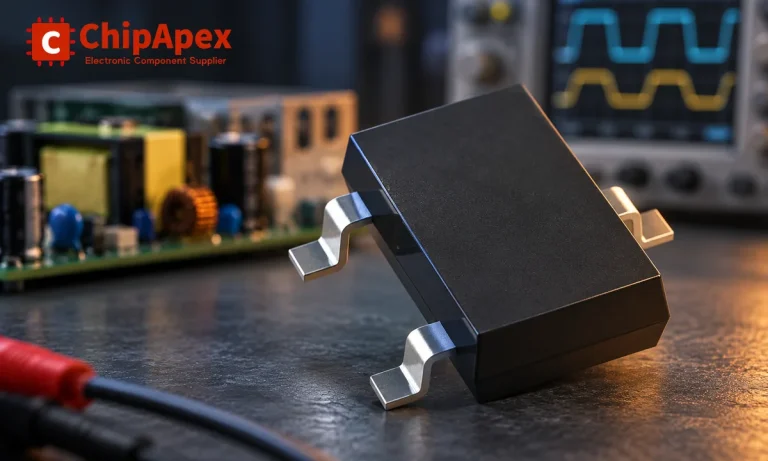
Learn how rectifiers convert AC to DC, compare half-wave and bridge circuits, and select voltage, current, recovery and thermal ratings for your design.
Read More
The activity of extra discounts on wholesale prices is in full swing…
Please fill in your contact information and we will send you the latest wholesale price list.





