 ChipApex | Global Electronic Components Supplier
AD7827BR
Search Product
Search Post
— IC芯片 | 连接器 | 传感器 | 被动器件 —
Search productSearch post
— IC芯片 | 连接器 | 传感器 | 被动器件 —
Consult the customer manager about the wholesale price.
consultation hotline:86-132-6715-2157
email:[email protected]
Contact the product manager for consultation. One-stop consultation is available.
Do you want a lower wholesale price? Please send us your inquiry and we will reply immediately.
The AD7827BR is an 8-bit, single-channel analog-to-digital converter (ADC) featuring a half-flash architecture and a maximum throughput of 1 MSPS. It operates from a single 3 V or 5 V supply with an input range of 0 V to 2 V or 0 V to 2.5 V, respectively. The device integrates a track-and-hold amplifier, a 2.5 V reference with 2% tolerance, and a serial interface compatible with DSPs. Key electrical parameters include a conversion time of 420 ns, acquisition time of 200 ns, SNR of 48 dB min, INL/DNL of ±0.5 LSB max, and power dissipation of 30 mW max at normal operation.
Verify the specific package variant, as the BR suffix denotes the SOIC-8 option while BN indicates Plastic DIP. Confirm that the B version meets the required industrial temperature range of -40°C to +105°C. Ensure the ordering documentation matches the exact part number to avoid confusion with other series members like the AD7825 or AD7829.
Select this component when a single-channel, low-power ADC with integrated reference and track-and-hold is required. The choice between 3 V and 5 V operation dictates the analog input voltage span. Consider the automatic power-down mode if average power consumption must be minimized below the standard 30 mW active level.
The AD7827 belongs to Analog Devices' family of high-speed, low-power sampling ADCs. It utilizes a half-flash architecture to achieve 8-bit resolution with fast conversion times. This model is designed for applications where space and power are constrained, offering a compact solution compared to discrete track-and-hold and ADC combinations.
Publicly confirmed substitute part numbers are not available in the provided documentation. Verify compatibility with existing designs before considering alternative models within the manufacturer's portfolio.
An on-chip VDD detector circuit automatically sets the input range. It detects 5 V operation when VDD exceeds 4.1 V (0 V to 2.5 V range) and 3 V operation when VDD falls below 3.8 V (0 V to 2 V range).
The state of the CONVST pin is sampled approximately 530 ns after the falling edge of the CONVST pulse. If CONVST is low at this point, the device powers down; it powers up again on the next rising edge of CONVST.
The RFS (Receive Frame Sync) signal goes logic low on the first rising edge of SCLK after conversion ends. Data bits are shifted out on subsequent rising edges of SCLK, and DOUT enters high impedance after the eighth bit.
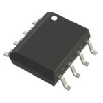 AD7827BR
The activity of extra discounts on wholesale prices is in full swing…
Please fill in your contact information and we will send you the latest wholesale price list.




