 ChipApex | Global Electronic Components Supplier

SEARCH
Search Product
Search Post
— IC芯片 | 连接器 | 传感器 | 被动器件 —
Search productSearch post
— IC芯片 | 连接器 | 传感器 | 被动器件 —
Consult the customer manager about the wholesale price.
consultation hotline:86-132-6715-2157
email:[email protected]
Contact the product manager for consultation. One-stop consultation is available.
Do you want a lower wholesale price? Please send us your inquiry and we will reply immediately.
ADS7811U-1/1K is listed in the Analog To Digital Converters (ADC) range at ChipApex. The manufacturer field lists Texas Instruments. Its product description is PROTOTYPE. Review the specifications below when checking this part for your BOM.
The ADS7811U-1/1K is a 16-bit CMOS analog-to-digital converter featuring a 250kHz throughput rate. It integrates a capacitor-based successive approximation register (SAR) architecture with an inherent sample-and-hold circuit, a precision reference, and an internal clock. The device operates on dual ±5V supplies, providing a ±2.5V input range. Key electrical specifications include a minimum spurious-free dynamic range of 96dB at a 100kHz input frequency, a signal-to-noise plus distortion ratio of 84dB, and a typical full-scale error of ±0.5%. It utilizes parallel binary two's complement data output.
Verify the specific ordering suffix against the manufacturer's current Package Option Addendum to confirm packaging type and material compliance. Confirm that the requested quantity aligns with the standard shipping carrier specifications defined in the official documentation. Ensure all technical parameters match the design requirements before finalizing the purchase order.
Select this component when a 16-bit resolution and 250kHz sampling speed are required within a single-chip solution. The integrated reference and clock simplify board layout compared to discrete architectures. Ensure the application can accommodate the necessary ±5V power supply rails and provides adequate drive capability for the parallel digital interface.
This device belongs to the ADS7811 family of high-performance analog-to-digital converters manufactured by Texas Instruments. It represents a specialized class of CMOS SAR converters designed for applications demanding high linearity and wide dynamic range without the complexity of multi-channel simultaneous sampling architectures.
Consult the official datasheet for listed similar part numbers such as the ADS7813 or ADS7815. Verify pin compatibility and electrical specifications before substitution, as interface timing and resolution may differ across the product family.
To initiate a conversion, take the R/C pin LOW at least 100ns before taking the CS pin LOW. Both signals should be returned HIGH during the early part of the conversion cycle to prevent noise coupling onto the hold capacitor.
During the conversion cycle, the digital outputs (D15 through D0) enter a high-impedance state. They become active again near the end of the conversion, allowing the result to be latched upon the rising edge of the BUSY signal.
Yes, an external reference can be applied to the REF pin to bypass the internal reference. However, the device specifications are only guaranteed when the internal reference is utilized.
Explore related parts through Data Acquisition, Integrated Circuits (ICs), all product categories, ChipApex homepage.
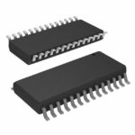 ADS7811U-1/1K
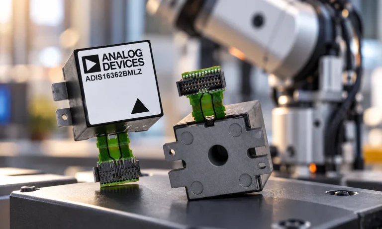
Learn what an IMU measures, how accelerometers and gyroscopes work together, why orientation estimates drift, and what to compare.
Read More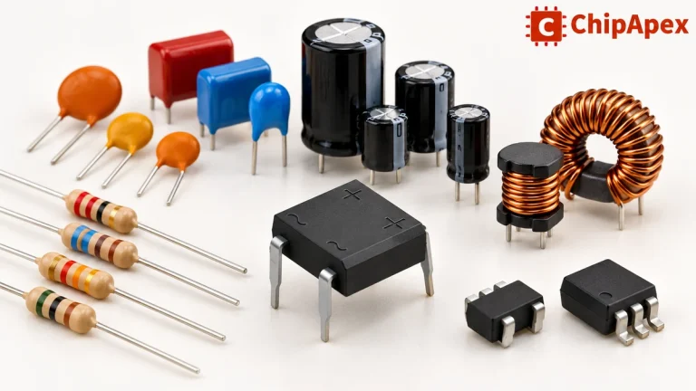
Explore electronic component types, functions, packages and datasheets. Learn selection, replacement and BOM checks before ordering parts for your PCB.
Read More
ADS7811U-1/1K is listed in the Analog To Digital Converters (ADC) range at ChipApex. The manufacturer field lists Texas Instruments. Its product description is PROTOTYPE.…
Read More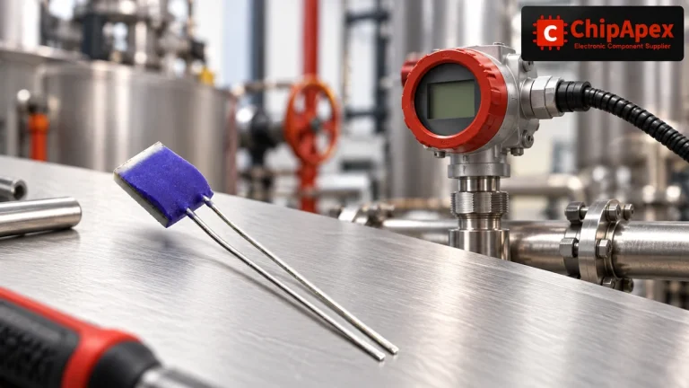
Compare Pt100 and Pt1000 RTDs, two-, three- and four-wire connections, excitation and self-heating. Build an error budget from element to reported temperature.
Read More
ADS7811U-1/1K is listed in the Analog To Digital Converters (ADC) range at ChipApex. The manufacturer field lists Texas Instruments. Its product description is PROTOTYPE.…
Read More
ADS7811U-1/1K is listed in the Analog To Digital Converters (ADC) range at ChipApex. The manufacturer field lists Texas Instruments. Its product description is PROTOTYPE.…
Read More
ADS7811U-1/1K is listed in the Analog To Digital Converters (ADC) range at ChipApex. The manufacturer field lists Texas Instruments. Its product description is PROTOTYPE.…
Read More
ADS7811U-1/1K is listed in the Analog To Digital Converters (ADC) range at ChipApex. The manufacturer field lists Texas Instruments. Its product description is PROTOTYPE.…
Read More
ADS7811U-1/1K is listed in the Analog To Digital Converters (ADC) range at ChipApex. The manufacturer field lists Texas Instruments. Its product description is PROTOTYPE.…
Read More
ADS7811U-1/1K is listed in the Analog To Digital Converters (ADC) range at ChipApex. The manufacturer field lists Texas Instruments. Its product description is PROTOTYPE.…
Read More
ADS7811U-1/1K is listed in the Analog To Digital Converters (ADC) range at ChipApex. The manufacturer field lists Texas Instruments. Its product description is PROTOTYPE.…
Read More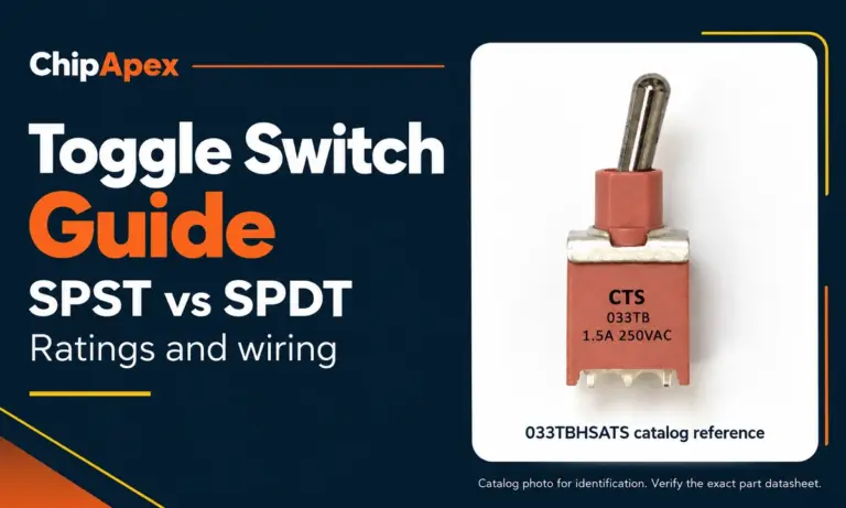
Compare SPST and SPDT toggle switches, understand AC/DC ratings, and follow wiring examples. Check contact action, mounting and parts in the ChipApex catalog.
Read More
The activity of extra discounts on wholesale prices is in full swing…
Please fill in your contact information and we will send you the latest wholesale price list.




