 ChipApex | Global Electronic Components Supplier

SEARCH
Search Product
Search Post
— IC芯片 | 连接器 | 传感器 | 被动器件 —
Search productSearch post
— IC芯片 | 连接器 | 传感器 | 被动器件 —
Consult the customer manager about the wholesale price.
consultation hotline:86-132-6715-2157
email:[email protected]
Contact the product manager for consultation. One-stop consultation is available.
Do you want a lower wholesale price? Please send us your inquiry and we will reply immediately.
BAP51-06W,115 is listed in the RF Diode range at ChipApex. The manufacturer field lists NXP USA Inc.. Its product description is RF DIODE PIN 50V 240MW SC-70. Review the specifications below when checking this part for your BOM.
The BAP51-06W is a silicon PIN diode featuring two planar elements in a common anode configuration, housed in an SOT323 small surface-mount plastic package. It is qualified to AEC-Q101 standards for automotive reliability. Key electrical parameters include a maximum reverse voltage of 50 V and a maximum forward current of 50 mA. The device exhibits low diode capacitance, ranging from 0.2 pF to 0.55 pF depending on bias conditions, and low forward resistance, typically 1.5 Ω at 10 mA. Total power dissipation is rated at 240 mW with a junction-to-solder point thermal resistance of 250 K/W.
Verify the specific ordering suffix (e.g., 115) against the manufacturer's official documentation to confirm reel size or tape-and-reel specifications. Ensure the component meets the required AEC-Q101 automotive qualification standards if deployed in vehicle systems. Cross-reference the SOT323 package dimensions with PCB footprint requirements prior to procurement.
Select this component when a dual-diode solution with a shared anode terminal is required in space-constrained designs. The SOT323 package offers a small footprint suitable for high-density mounting. Consider the 50 V reverse voltage and 50 mA forward current limits to ensure operation remains within absolute maximum ratings during circuit design.
This part belongs to NXP's portfolio of silicon PIN diodes designed for radio frequency applications. The BAP51 series provides solutions for attenuators and switches. The BAP51-06W specifically utilizes the SOT323 package, distinguishing it from other variants that may use different form factors while maintaining similar electrical characteristics.
Check for direct substitutes such as the BAP51-05W or BAP51LX, noting differences in pin count and package type (UMT vs. SOD-882). Verify that any replacement maintains the common anode configuration and AEC-Q101 qualification if automotive compliance is mandatory.
The typical charge carrier lifetime is 0.55 µs, measured under specific bias conditions where IF = 10 mA and IR = 6 mA.
At 1 MHz, the typical capacitance decreases as reverse voltage increases: approximately 0.4 pF at 0 V, 0.3 pF at 1 V, and 0.2 pF at 5 V.
The typical isolation at 2450 MHz is -12 dB when the diode is zero-biased.
Explore related parts through Diodes, Discrete Semiconductor Products, all product categories, ChipApex homepage.
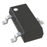 BAP51-06W,115
Choose logic inverter ICs by thresholds, supply, output drive and delay. Compare standard and Schmitt-trigger inputs, power sequencing and replacement checks.
Read More
BAP51-06W,115 is listed in the RF Diode range at ChipApex. The manufacturer field lists NXP USA Inc.. Its product description is RF DIODE PIN…
Read More
BAP51-06W,115 is listed in the RF Diode range at ChipApex. The manufacturer field lists NXP USA Inc.. Its product description is RF DIODE PIN…
Read More
BAP51-06W,115 is listed in the RF Diode range at ChipApex. The manufacturer field lists NXP USA Inc.. Its product description is RF DIODE PIN…
Read More
BAP51-06W,115 is listed in the RF Diode range at ChipApex. The manufacturer field lists NXP USA Inc.. Its product description is RF DIODE PIN…
Read More
BAP51-06W,115 is listed in the RF Diode range at ChipApex. The manufacturer field lists NXP USA Inc.. Its product description is RF DIODE PIN…
Read More
BAP51-06W,115 is listed in the RF Diode range at ChipApex. The manufacturer field lists NXP USA Inc.. Its product description is RF DIODE PIN…
Read More
BAP51-06W,115 is listed in the RF Diode range at ChipApex. The manufacturer field lists NXP USA Inc.. Its product description is RF DIODE PIN…
Read More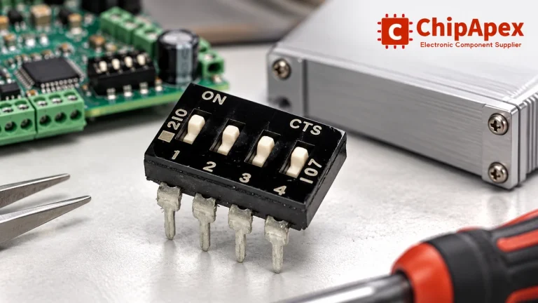
Choose a DIP switch by contact type, coded positions, footprint and signal ratings. Check logic polarity, assembly conditions and PCB configuration behavior.
Read More
BAP51-06W,115 is listed in the RF Diode range at ChipApex. The manufacturer field lists NXP USA Inc.. Its product description is RF DIODE PIN…
Read More
BAP51-06W,115 is listed in the RF Diode range at ChipApex. The manufacturer field lists NXP USA Inc.. Its product description is RF DIODE PIN…
Read More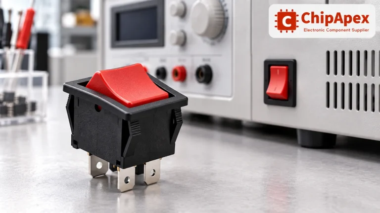
Choose a rocker switch by AC/DC ratings, contact arrangement, illumination, panel fit and sealing. Get practical checks for engineering and component sourcing.
Read More
The activity of extra discounts on wholesale prices is in full swing…
Please fill in your contact information and we will send you the latest wholesale price list.




