 ChipApex | Global Electronic Components Supplier

SEARCH
Search Product
Search Post
— IC芯片 | 连接器 | 传感器 | 被动器件 —
Search productSearch post
— IC芯片 | 连接器 | 传感器 | 被动器件 —
Consult the customer manager about the wholesale price.
consultation hotline:86-132-6715-2157
email:[email protected]
Contact the product manager for consultation. One-stop consultation is available.
Do you want a lower wholesale price? Please send us your inquiry and we will reply immediately.
CLA4607-085LF is listed in the RF Diode range at ChipApex. The manufacturer field lists Skyworks Solutions Inc.. Its product description is RF DIODE PIN 180V 13W 3QFN. Review the specifications below when checking this part for your BOM.
The CLA4607-085LF is a surface-mountable, low-capacitance silicon PIN limiter diode designed for shunt-connected high-power limiter applications from 10 MHz to over 6 GHz. It features a nominal threshold level of +20 dBm and an I-region width of 7 um. Key electrical specifications include a maximum reverse voltage (VR) of 180 V, a forward current (IF) of 1.5 A at 25 °C, and a CW power dissipation (PD) of 1.3 W. The device exhibits a typical capacitance of 0.35 pF at 38 V and 1 MHz, with a series resistance of 2.0 Ω max at 10 mA and 500 MHz. Thermal performance includes a junction-to-case thermal resistance of 54 °C/W. Operating temperature ranges from -55 °C to +150 °C.
Verify the specific ordering suffix against official Skyworks documentation to ensure correct packaging configuration. Confirm compliance requirements such as RoHS status and Moisture Sensitivity Level (MSL1) prior to procurement. Ensure handling procedures account for electrostatic discharge (ESD) precautions during storage and transport.
Select this component for shunt-connected applications requiring low insertion loss and high power handling up to 6 GHz. Evaluate the 7 um I-region width and 54 °C/W thermal resistance against system heat sinking capabilities. Verify that the 180 V reverse voltage rating exceeds peak circuit voltages.
This part belongs to the CLA4607 series of surface-mount limiter diodes manufactured by Skyworks Solutions, Inc. It is specifically engineered for RF receiver protection circuits where minimal signal distortion and effective high-power limiting are required within compact form factors.
Publicly confirmed substitute part numbers are not available in the provided datasheet or verified local source material.
During limiting, a DC current is generated by charge carriers forced into the I layer by the forward alternations of the large input signal. A complete path must be provided for this current using an RF choke or similar structure.
It is recommended to place several vias under the entire footprint of the exposed paddle (pin 2) to minimize both electrical inductance to system ground and thermal resistance to the system heat sink.
The recovery time is 50 ns, defined as the transition time from the high-loss state to the low-loss state following the removal of a high-power input pulse.
Explore related parts through Diodes, Discrete Semiconductor Products, all product categories, ChipApex homepage.
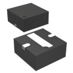 CLA4607-085LF

CLA4607-085LF is listed in the RF Diode range at ChipApex. The manufacturer field lists Skyworks Solutions Inc.. Its product description is RF DIODE PIN…
Read More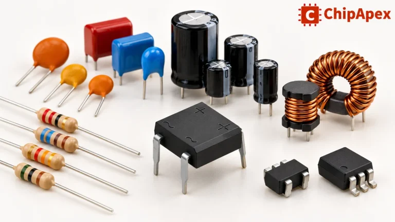
Explore electronic component types, functions, packages and datasheets. Learn selection, replacement and BOM checks before ordering parts for your PCB.
Read More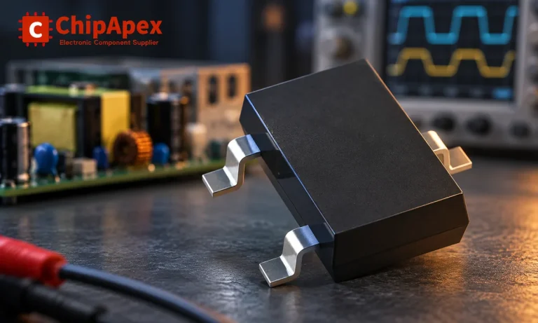
Learn how rectifiers convert AC to DC, compare half-wave and bridge circuits, and select voltage, current, recovery and thermal ratings for your design.
Read More
CLA4607-085LF is listed in the RF Diode range at ChipApex. The manufacturer field lists Skyworks Solutions Inc.. Its product description is RF DIODE PIN…
Read More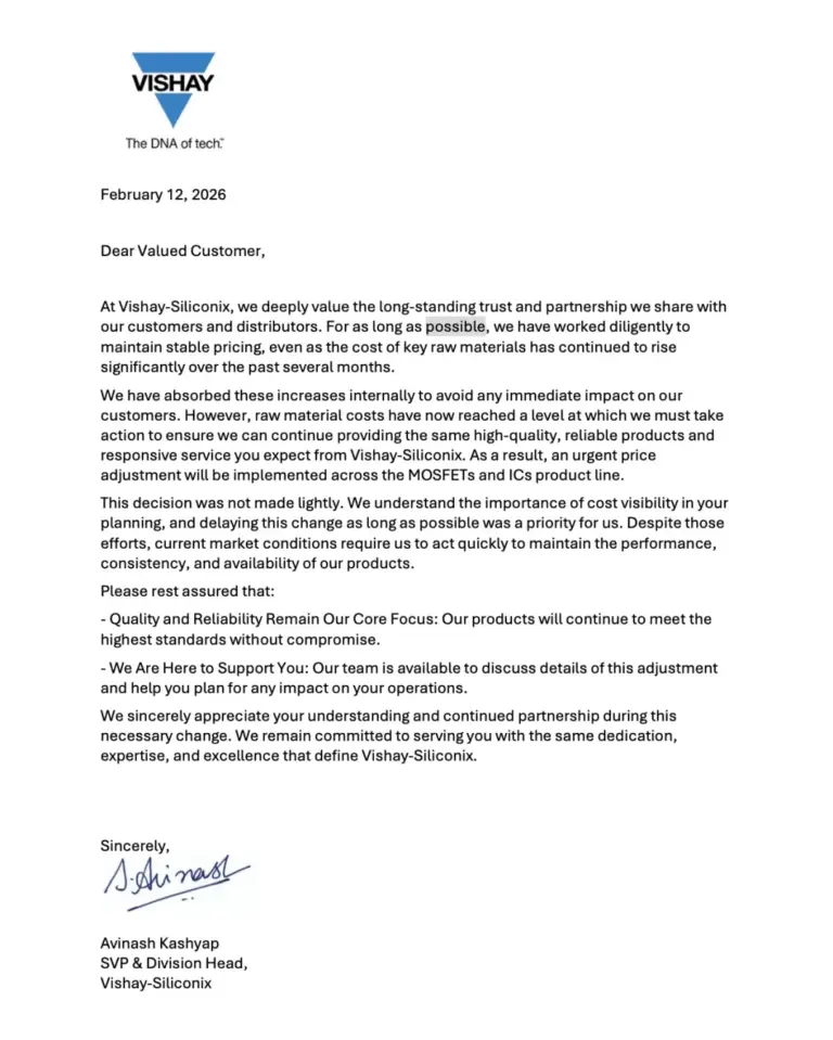
CLA4607-085LF is listed in the RF Diode range at ChipApex. The manufacturer field lists Skyworks Solutions Inc.. Its product description is RF DIODE PIN…
Read More
CLA4607-085LF is listed in the RF Diode range at ChipApex. The manufacturer field lists Skyworks Solutions Inc.. Its product description is RF DIODE PIN…
Read More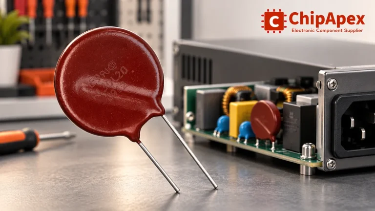
Select MOV varistors by continuous voltage, clamping behavior, surge waveform and repetition. Check thermal disconnection, fuse coordination and replacements.
Read More
CLA4607-085LF is listed in the RF Diode range at ChipApex. The manufacturer field lists Skyworks Solutions Inc.. Its product description is RF DIODE PIN…
Read More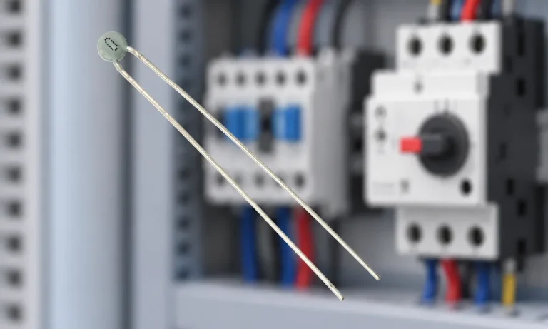
Learn why PTC resistance rises with temperature, how it differs from NTC, and which ratings matter for sensing and protection.
Read More
CLA4607-085LF is listed in the RF Diode range at ChipApex. The manufacturer field lists Skyworks Solutions Inc.. Its product description is RF DIODE PIN…
Read More
CLA4607-085LF is listed in the RF Diode range at ChipApex. The manufacturer field lists Skyworks Solutions Inc.. Its product description is RF DIODE PIN…
Read More
CLA4607-085LF is listed in the RF Diode range at ChipApex. The manufacturer field lists Skyworks Solutions Inc.. Its product description is RF DIODE PIN…
Read More
The activity of extra discounts on wholesale prices is in full swing…
Please fill in your contact information and we will send you the latest wholesale price list.




