 ChipApex | Global Electronic Components Supplier

SEARCH
Search Product
Search Post
— IC芯片 | 连接器 | 传感器 | 被动器件 —
Search productSearch post
— IC芯片 | 连接器 | 传感器 | 被动器件 —
Consult the customer manager about the wholesale price.
consultation hotline:86-132-6715-2157
email:chipapex@foxmail.com
Contact the product manager for consultation. One-stop consultation is available.
Do you want a lower wholesale price? Please send us your inquiry and we will reply immediately.
DCE10I-2451-FSMF is listed in the Antennas RF range at ChipApex. The manufacturer field lists TE Connectivity. Its product description is RF ANT 2.4GHZ/5GHZ PANEL BRKT MT. Review the specifications below when checking this part for your BOM.
DCE10I-2451-FSMF is a panel-mount antenna system manufactured by Laird Technologies, designed for dual-band operation in the 2.4 GHz and 5 GHz frequency ranges. The unit features a die-cast enclosure with an integrated high-gain panel antenna, providing 12 dBi gain at 2.4 GHz and 19 dBi gain at 5 GHz. It supports frequencies from 2.4 GHz to 2.485 GHz and 4.9 GHz to 5.85 GHz, with a maximum power handling of 100 W. The antenna utilizes SMA female connectors via a 203 mm pigtail cable and offers IP67 ingress protection. VSWR values are specified as 2.0 and 1.7 for the respective bands.
Verify component authenticity through authorized TE Connectivity or Laird Technologies distribution channels. Confirm specific manufacturing date codes and revision levels against current technical documentation. Ensure environmental ratings match installation requirements. Validate connector types and cable lengths prior to order placement. Request official test reports for compliance verification.
Evaluate gain requirements against spatial constraints and mounting orientation. Assess IP67 rating suitability for outdoor or harsh industrial environments. Consider pole or wall mounting options based on site geometry. Verify compatibility with existing radio equipment using the provided SMA female interface. Review tilt bracket availability if directional adjustment is necessary.
This model belongs to the HD RooTenna series, offering flexible antenna system configurations. It serves as an alternative to standalone enclosures or low-gain integrated options within the same product family. The design emphasizes spectral flexibility and robust physical construction for reliable wireless connectivity in demanding applications.
Consult official manufacturer documentation for direct substitute part numbers. Verify equivalent electrical performance and mechanical dimensions before substitution. Ensure compatibility with existing mounting hardware and cabling interfaces. Cross-reference updated datasheets for any functional changes in newer revisions.
Explore related parts through RF and Wireless, all product categories, ChipApex homepage.
 DCE10I-2451-FSMF
DCE10I-2451-FSMF is listed in the Antennas RF range at ChipApex. The manufacturer field lists TE Connectivity. Its product description is RF ANT 2.4GHZ/5GHZ PANEL…
Read More
DCE10I-2451-FSMF is listed in the Antennas RF range at ChipApex. The manufacturer field lists TE Connectivity. Its product description is RF ANT 2.4GHZ/5GHZ PANEL…
Read More
Learn how a pressure transducer converts pressure into voltage, current, or digital output, and compare pressure references and key selection specs.
Read More
DCE10I-2451-FSMF is listed in the Antennas RF range at ChipApex. The manufacturer field lists TE Connectivity. Its product description is RF ANT 2.4GHZ/5GHZ PANEL…
Read More
Learn why PTC resistance rises with temperature, how it differs from NTC, and which ratings matter for sensing and protection.
Read More
DCE10I-2451-FSMF is listed in the Antennas RF range at ChipApex. The manufacturer field lists TE Connectivity. Its product description is RF ANT 2.4GHZ/5GHZ PANEL…
Read More
Understand RF attenuator dB values, fixed and programmable types, impedance, power limits and noise tradeoffs before choosing parts for an RF signal path.
Read More
DCE10I-2451-FSMF is listed in the Antennas RF range at ChipApex. The manufacturer field lists TE Connectivity. Its product description is RF ANT 2.4GHZ/5GHZ PANEL…
Read More
DCE10I-2451-FSMF is listed in the Antennas RF range at ChipApex. The manufacturer field lists TE Connectivity. Its product description is RF ANT 2.4GHZ/5GHZ PANEL…
Read More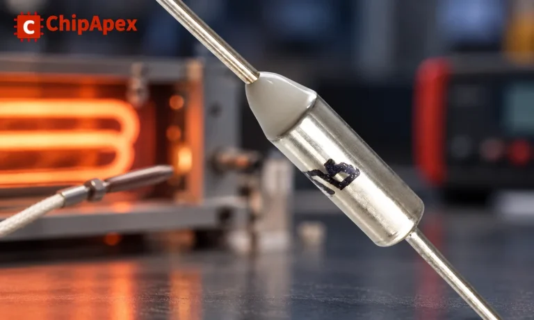
Understand thermal fuse operation, Tf, Th and Tm, electrical ratings and mounting. Check temperature limits and replacement requirements for your design.
Read More
DCE10I-2451-FSMF is listed in the Antennas RF range at ChipApex. The manufacturer field lists TE Connectivity. Its product description is RF ANT 2.4GHZ/5GHZ PANEL…
Read More
DCE10I-2451-FSMF is listed in the Antennas RF range at ChipApex. The manufacturer field lists TE Connectivity. Its product description is RF ANT 2.4GHZ/5GHZ PANEL…
Read More
The activity of extra discounts on wholesale prices is in full swing…
Please fill in your contact information and we will send you the latest wholesale price list.




