 ChipApex | Global Electronic Components Supplier

SEARCH
Search Product
Search Post
— IC芯片 | 连接器 | 传感器 | 被动器件 —
Search productSearch post
— IC芯片 | 连接器 | 传感器 | 被动器件 —
Consult the customer manager about the wholesale price.
consultation hotline:86-132-6715-2157
email:[email protected]
Contact the product manager for consultation. One-stop consultation is available.
Do you want a lower wholesale price? Please send us your inquiry and we will reply immediately.
FMU-14S is listed in the Diode Arrays range at ChipApex. The manufacturer field lists Sanken Electric USA Inc.. Its product description is DIODE ARRAY GP 400V 5A TO-220F. Review the specifications below when checking this part for your BOM.
The FMU-14S is a silicon rectifier diode designed for high-frequency rectification applications. It features a resin-molded structure with an isolated case connection. Key electrical ratings include a peak reverse voltage of 400 V and a maximum average forward current of 5.0 A, subject to derating curves based on case temperature. The device supports a transient peak reverse voltage of 450 V and a peak surge forward current of 30 A. Electrical characteristics specify a maximum forward voltage drop of 1.5 V at 2.5 A and a reverse recovery time ranging from 180 ns to 400 ns depending on test conditions. Thermal resistance between the junction and case is limited to 4.0 °C/W.
Verify the specific suffix designation (e.g., R) against official documentation to confirm exact marking and package details. Confirm compliance with UL94V-0 flammability standards if required by the design specification. Ensure thermal management strategies account for the specified junction-to-case thermal resistance and derating requirements to maintain operation within the -40°C to +150°C junction temperature range.
Select this component for designs requiring fast recovery characteristics in high-frequency environments. Evaluate the thermal performance using the provided derating curves to ensure the average forward current remains within limits at expected operating case temperatures. Consider the 400 V peak reverse voltage rating relative to the circuit's maximum reverse voltage stress. Note that the manufacturer indicates this part is not recommended for new designs.
The FMU-14S belongs to Sanken Electric's lineup of silicon rectifier diodes. These components are engineered for robust performance in power conversion systems where rapid switching and high reliability are necessary. The product line typically includes variants optimized for different voltage and current thresholds while maintaining consistent physical dimensions and mounting characteristics.
Public confirmed substitute part numbers are not available in the provided documentation.
The maximum reverse recovery time is 400 ns when tested at IF=IRP=100mA with a 90% recovery point at Tj=25°C. Under conditions of IF=100mA and IRP=200mA at a 75% recovery point, the maximum time is 180 ns.
The average forward current must be reduced as the case temperature increases. The datasheet provides a derating curve showing the relationship between case temperature and allowable average forward current to keep the junction temperature within the +150°C limit.
The maximum thermal resistance between the junction and the case (Rth(j-c)) is 4.0 °C/W.
Explore related parts through Rectifiers, Diodes, Discrete Semiconductor Products, all product categories.
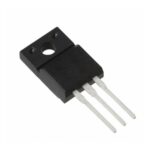 FMU-14S
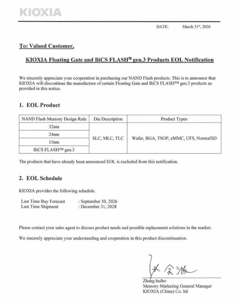
FMU-14S is listed in the Diode Arrays range at ChipApex. The manufacturer field lists Sanken Electric USA Inc.. Its product description is DIODE ARRAY…
Read More
Learn how a diode conducts, how to identify anode and cathode, and when to choose rectifier, TVS, Zener or photodiode types for a circuit.
Read More
FMU-14S is listed in the Diode Arrays range at ChipApex. The manufacturer field lists Sanken Electric USA Inc.. Its product description is DIODE ARRAY…
Read More
FMU-14S is listed in the Diode Arrays range at ChipApex. The manufacturer field lists Sanken Electric USA Inc.. Its product description is DIODE ARRAY…
Read More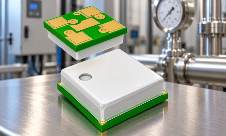
Learn how a pressure transducer converts pressure into voltage, current, or digital output, and compare pressure references and key selection specs.
Read More
Understand how oscillators generate timing signals, how they differ from crystals, and which frequency, output and stability specs matter when choosing one.
Read More
FMU-14S is listed in the Diode Arrays range at ChipApex. The manufacturer field lists Sanken Electric USA Inc.. Its product description is DIODE ARRAY…
Read More
See how a MEMS gyroscope measures angular rate, why its angle estimate drifts, and which range, noise, interface and temperature specs to compare.
Read More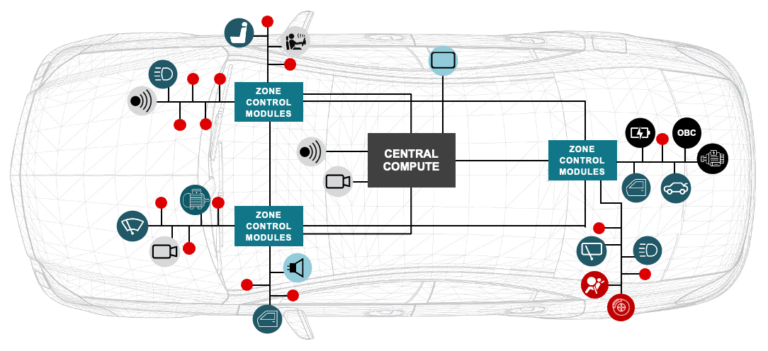
FMU-14S is listed in the Diode Arrays range at ChipApex. The manufacturer field lists Sanken Electric USA Inc.. Its product description is DIODE ARRAY…
Read More
FMU-14S is listed in the Diode Arrays range at ChipApex. The manufacturer field lists Sanken Electric USA Inc.. Its product description is DIODE ARRAY…
Read More
FMU-14S is listed in the Diode Arrays range at ChipApex. The manufacturer field lists Sanken Electric USA Inc.. Its product description is DIODE ARRAY…
Read More
FMU-14S is listed in the Diode Arrays range at ChipApex. The manufacturer field lists Sanken Electric USA Inc.. Its product description is DIODE ARRAY…
Read More
The activity of extra discounts on wholesale prices is in full swing…
Please fill in your contact information and we will send you the latest wholesale price list.





